
Supercapacitors are fascinating things and are getting better and better all the time.
They need balancing when charged in series to prevent differing capacitances causing full capacitors to over-volt while other are still filling.
This kind of capacitor has some ionic stuff going on inside, and they are easily ruined if their terminal voltage rises much above the nominal maximum – 2.7V in many cases.
The press release contains the expression: ‘includes a 2-stage active balancing circuit to ensure that voltage across each supercapacitor cell is approximately equal’.
Which to me suggests the circuit includes: an active potential divider making the capacitors charge together, as well as a shunt voltage limiter for each individual capacitor, although it maybe more complex – I am guessing the guys are black belts in balancing.
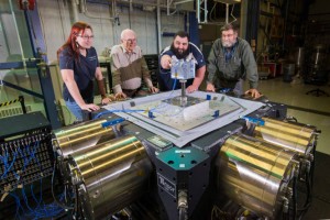
Having had a good look at the data sheet, the kit has three small pcbs and allows six capacitors to be connected in a series string.
Each balancer board has three connections – to both ends and the middle (yellow wire) of a series pair.
So as far as I can tell, and I may easily be wrong here, the kit is charging six capacitors in series as three series pairs, and there is no connection to balance between pairs.
So, afaik, within the series pairs the circuits both balance terminal voltage and limit maximum individual cell voltage.
But there is no attempt to even-out charging between the three pairs, – only to limit the six maximum cell voltages.
 Which has made me wonder what the advantage of capacitor charge balancing is.
Would there be an advantage in balancing all six of them as they charge, rather than just voltage-limiting them? And why not add a fourth connection to each board to optionally balance up and down the string? These questions have been passed to Kemet, with fingers crossed that I am not making a fool of myself.
Also, the data sheet doesn’t say what the maximum balancing current is.
BTW, what a neat mechanical design.
Kemet replies
I got an interesting phone call from technical marketing guy James Lewis of Kemet.
It looks like I was right about charge balancing within pairs, but not between pairs, and each cell being voltage limited.
According to James, balancing the individual charge of every cell in a pack with every other cell has advantages, but is overkill in most applications.
Cells will live for their predicted design life if they are limited to their maximum design voltage.
Life/voltage curves are such, that cells live longer if voltage is minimised, so complete inter-cell balancing does maximum pack life. But you have to pay for the added electronics.
A very interesting fact is that the life/voltage curve is non-linear, and cells limited to 2V max live much much longer so, if you can stand the 0.5CV2 capacity loss, packs can be helped to last a heck of a long time.
In the case above, I conclude, voltage limiting ensures all cells meet their design life (assuming no disasters) and, as the pcbs offer pair balancing anyway, pairs will live a little longer, so the whole pack is likely to live a little longer.
If your design only has one pair of cells, the pcb will help them to maximum life.
Ps, I forgot to ask about maximum balancing current 🙁