OCEAN MAPPING USES TO INCREASE ACCURACY
By John Haystead, Contributing Editor
United States Geological Survey (USGS) marine and coastal researchers are using sidescan sonar and image-processing techniques to map regions of the shallow Exclusive Economic Zone (EEZ). The EEZ, which extends 200 nautical miles from the US shoreline, was established by President Reagan to protect US fisheries and mineral resources. Based on a multibeam sonar survey, maps of the EEZ produced by the USGS Atlantic Geology Team at Woods Hole, MA, show sediment texture, rock types, pollutant concentrations, geological structures, and shipping hazards.
As the marine equivalent of aerial photography, sidescan sonar produces images that are pieced together to produce a mosaic of the ocean floor. To accomplish this, researchers at Woods Hole use a number of sonar transducer systems including the SIS-1000 single-beam, sidescan sonar from Datasonics (Cataumet, MA). The SIS-1000 is a swept-signal (or chirp) system that operates between 97 and 103 kHz with a variable pulse (or ping) rate from 1 to 8 pings/s, depending on the desired swath size. The SIS-1000 is towed above the sea floor at a height related to the range of the desired swath. "This is generally 10% of the range (or width)," says group geologist Bill Danforth, "so to generate a 200-m swath (100 m in each direction), the sonar is towed 10 m from the ocean bottom."
Pings from port- and starboard-mounted transducers are returned as echos--backscattered reflections of varying amplitudes from the sea floor--that are collected and converted into image mosaics. A time-varied gain is applied to each return to adjust for signal attenuation. An additional "sub-bottom" hydrophone beams directly downward from the sonar, penetrating into the sediment structure to provide information about the layering beneath the surface.
Operating range is related to ping rate and the speed of sound in water. The USGS survey team operates the system at 4 pings/s at a towing depth of 17 m above the sea floor. This translates into an approximate range of 175 m , or a 350-m total swath. Where total water depth is less than 20-25 m, the ping rate is increased to 8 pings/s, and the sonar is lowered to 9 m from the bottom for a 90-m range.
The objective of the survey program is to obtain as much detail as possible identifying very small geologic structures and potential hazards such as shipwrecks. Image resolution is based on ping rate, and, along with the 15-kHz digitizing rate of the integrated analog-to-digital conversion system on the SIS, provides the maximum number of samples that can be saved in the system.
At a 4-ping/s rate, the theoretical maximum number of (16 bit/2 byte) samples saved would be 15k/4 or 3750 per side. But because the system software samples data in power-of-two sample sizes, it saves only 2048 per side (4096 samples/swath). This translates to an average resolution of 175/3750 or 0.085 m/sample/ping. Total resolution can be improved by increasing the ping rate, or alternatively, the same resolution can be maintained at longer ranges by decreasing the ping rate to a minimum of 1 ping/s for a maximum sampling rate of 8192 samples per side.
Another factor affecting resolution is the signal pulsewidth. Although there are more samples returned at near ranges, resolution is better at greater distances from the sonar because the pulsewidth or flatness of the signal wavefront relative to sea-bottom features decreases as it moves away from the sonar.
Image processing
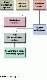
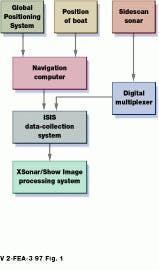
Sonar data from the SIS are fed into a Datasonics multiplexer where they are separated into three channels: port, starboard, and sub-bottom information (see Fig. 1). Each channel is fed to the AT&T DSP board that performs data filtering. This board is housed in Isis, a Windows 95-based Pentium PC from Triton Technologies (Watsonville, CA). Here, data are combined with differential GPS information from an on-board navigation computer. The result is a single data file that is passed to an Imagine 128 board from Number Nine Visual Technology (Lexington, MA) for data display.
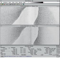
Datasonics SIS and Isis software are used in the Isis system to display sidescan sonar information in a waterfall fashion on a 1280 ¥ 1024 color monitor in real time (see Fig. 2). Multiple windows can show navigation parameter information, ship speed, pitch roll, and heading. A display menu controls parameters such as scale lines, delay, duration, and speed correction for individual channels.
In the past, Isis-generated sonar data were stored on Hewlett-Packard hard drives or 8-mm tape from Exabyte (Boulder, CO). Now the system is equipped with Ethernet boards from 3-Com (Santa Clara, CA) that network the system to one or more UNIX-based Silicon Graphics Indigo II computers, where image processing and initial sidescan-sonar mosaic maps of the sea floor are created. Mosaics are generated by an in-house-developed X-Windows software system called Xsonar/Show Image. Additional X-terminals serve as workstations for other shipboard analysts.
"The on-board capability to mosaic saves us both time and money because we can immediately see where our coverage was. It also provides a roadmap for follow-on sediment-collection operations from the sea floor while we`re still at sea," says Danforth.
Mosaic maps
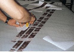
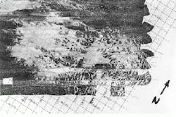
Sonar mosaic geographically registers each swath of sonar information to detailed navigation and heading information. Field mosaics are manually placed line by line on grid patterns as swath information from the sidescan sonar is processed by the Xsonar/Show Image software (see Fig. 3). More detailed mosaics are generated at Woods Hole using EASI/PACE remote-sensing software from PCI (Toronto, Canada). EASI/PACE allows image classification, geometric correction, enhancement, filtering, and terrain analysis and visualization and provides multiband image display, roam, and pseudo-color editing capabilities..
EASI/PACE is used to ensure that images of different resolutions are correctly referenced to the Earth. Four types of registration are possible: image to image, image to map, image to vector, and image to terminal coordinates. Pixel sizes can be resampled so that input data with varying resolutions can be stored together for further processing. Images can be "mosaiced" and blended along arbitrary cut lines and histogram-matched.
Danforth is satisfied with the performance and capabilities of the system. "Before we purchased the system, we viewed data on paper recorders," he says. Both software and hardware of the system continue to be upgraded to increase speed and resolution. Danforth points to the efficiency of the Ethernet that is used to download data to the UNIX system as an example. "We can now interpret data as soon as a file is closed." Also, the portability of the workstation/PC-based system has proven beneficial because the team uses chartered vessels for its surveying operations. "We can entirely outfit a mission and be underway in a matter of days," he says.
FIGURE 1. To form images of the ocean floor, sidescan sonar data are routed through a Datasonics multiplexer to the Isis image-processing system. Isis correlates and formats these data together with GPS and ship-orientation information. The data are then passed to Silicon Graphic`s Indigo II workstations for processing into mosaic imagery on-board ship.
FIGURE 2. Isis software running under Windows allows independent processing and display of each acquired data channel. Here, an image of a coastal shoal taken from 77 m is shown as a multiple-channel, vertical-waterfall sidescan-sonar display.
FIGURE 3. While on-board ship, survey team members place sidescan sonar output files onto a grid pattern to form field mosaics (left). This allows sonar data to be rapidly analyzed by researchers on-board ship. Analysis is later performed digitally at Wood`s Hole, MA, using EASI/PACE remote-sensing software.
Specialized sonar studies Stellwagen bank
Although the USGS team`s single-beam, towed sonars are adequate for many tasks, a more capable system was required to study Stellwagen Bank, a national marine sanctuary and key feeding area for endangered North Atlantic right whales. Stellwagen concerns US government and commercial interests because of its rich mineral and fishery resources. The aim of the survey was to understand the relationships between wildlife and the effects of trawling, dredging, and natural disturbances on sea-floor environments.
To examine the ocean floor, NOAA used the Canadian Hydrographic Service`s Fredrick Creed survey vessel equipped with a Simrad (Lynnwood, WA) multibeam side scan sonar. Unlike single-beam systems, the multibeam Simrad system provides depth-sounding data and topographic information from the same sonar signal. Even so, the survey, which involved mapping 1050 square nautical miles, took three years to complete.
The Simrad sonar operates at 95 kHz, with a total-water-depth-dependent variable ping rate. For the Stellwagen project, ping rate was set at 2-3 pings/s, with each formed into 60 distinct signal beams (30 on each side of the transducer) for every sounding of the sea floor. The average return time of each reflected beam is collected and correlated to calculate ocean depth, while the amplitude of the beams provides backscatter information for topographic imaging.
Each sounding sample is a 4-byte floating-point value with a total of 2000 samples/ping collected and saved on the system computer. In each time series, backscatter reflectance of the sea floor is computed from sonar data and represented on a 0-255 gray-scale spectrum.
PCs collect Global Positioning System data and ship-motion sensor information and transmit this to a Sun workstation together with sonar information. The Sun workstation incorporates this information into a single file and saves it to disk. Engineers access the information on Silicon Graphics Indigo II computers and display it as navigation, sound velocity profile, sounding, and backscatter information.
