The following is an excerpt from Multiphysics Simulation 2017.
By Valerio Marra
Despite significant addition to power generation and transmission capacities in recent years, India still faces an energy deficit of 2.1% and about 20,000 villages are off-grid. Moreover, electricity supply to urban and rural India is still unreliable. As a result, diesel generators are widely used for decentralized power generation. These generators (Figure 1, top), although inexpensive, are inefficient and pose great environmental and health risks.
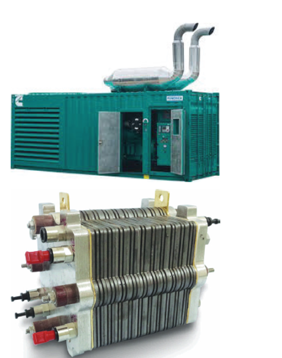 Figure 1. Top: Diesel generators used to power telecommunications towers in India. Bottom: PEM fuel cell.
This is why the National Chemistry Laboratory (NCL) in India, along with two other labs in the Council of Scientific and Industrial Research (CSIR), the Central Electrochemical Research Institute (CECRI), and the National Physical Laboratory (NPL), are investigating cleaner, cost-effective, and more dependable technology for powering telecom towers and eventually buildings.
A promising answer to the cost and pollution conundrum can be found in proton exchange membrane fuel cells (PEM fuel cells or PEMFCs, shown in Figure 1, bottom), which are being phased into many applications as replacements for older power technology. Thanks to their small carbon footprints, low decibel levels, fuel compatibility, and excellent complementarity with other renewable energy options, they have potential for use in transportation, residential buildings and offices, and certain industrial sectors. PEM fuel cell systems have an overall efficiency exceeding 30% (compared to 22-25% for diesel generators), and when run on pure hydrogen, their only emission is water vapor.
INSIDE A PEM FUEL CELL
PEM fuel cells contain a membrane electrode assembly (MEA) that comprises gas diffusion layers, electrodes, and polymer electrolyte membrane. Electrochemical reactions that generate power occur inside the MEA.
In a single PEM fuel cell, hydrogen streams to the anode side of the assembly, where it is split into protons and electrons by reactions in the presence of a catalyst. A network of carbon nanoparticles in the electrode conducts the electrons, providing current output to power a device before they reach the cathode on the other side. Meanwhile, protons travel through a proton exchange membrane and oxygen from air diffuses through a gas diffusion layer (GDL) in the MEA to reach the cathode (Figure 2).
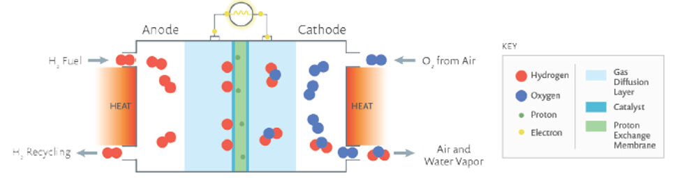 Figure 2. Concept of a PEM fuel cell. Hydrogen enters the anode where it reacts on the catalyst’s active sites to split into protons and electrons. Electrons are conducted through an external circuit over a load to the cathode, while the protons migrate to the cathode through the proton exchange membrane electrolyte. The PEM is made of a solid polymer that conducts protons but not electrons.
The protons react with oxygen and electrons at the catalyst’s active sites on the cathode to form water; the byproducts of the reactions are simply water and heat. Multiple such cells connected in series make a PEM fuel cell stack (Figure 3).
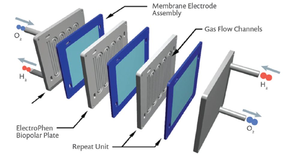 Figure 3. An example of a PEM fuel cell stack, which includes several layers of repeated units.
The power output and efficiency of the fuel cell is determined by many factors, such as catalytic activity of the active layers at the anode and cathode, the ability of the electrodes to transport liquid water out of the gas diffusion electrodes, the conductivity and porosity of the carbon network, the transport of reactant gases to the catalyst, the proton conductivity of the PEM, and the electrical conductivity of the bipolar plates.
CONFIGURING FOR MAXIMUM EFFICIENCY
The trick when choosing a PEM fuel cell for India’s telecom towers is to find the best configuration for maximum efficiency, knowing that improving the design in one area might reduce the effectiveness of another. For example, increasing porosity in the GDL allows hydrogen and air to enter more freely and moisture to leave more freely, but might decrease electrical conductivity.
Dr. Ashish Lele, chief scientist on the project at NCL, leads a team that has simulated and analyzed different configurations to find the optimal combination of properties in the PEM fuel cells intended for India’s telecom towers. “We wanted to understand the reactions at the carbon electrode and study how the transport of reacting gases and protons in the electrodes would modulate the overall reaction rate,” he explains. “We were ultimately interested in understanding how various parameters, such as operating conditions, flow field geometry, and MEA structural parameters influence the overall PEM fuel cell performance.”
Lele and his team modeled the convection of reactant gases in the flow field along with simultaneous reactions occurring at the catalyst layers and proton conduction through the PEM fuel cell. They relied on the functionality of the COMSOL Multiphysics® software for modeling chemical reactions and electrochemical impedance spectroscopy (EIS). EIS is used for characterizing electrochemical systems through measuring impedance and frequency response. The sidebar below gives a brief overview of modeling EIS in the COMSOL® software.
“The nature of COMSOL allowed us to include mass balance, momentum balance, species balance, and charge balance together,” he says. “We ran a sensitivity analysis on different parameters — for instance, design parameters such as the flow field shape, operating parameters such as back pressure and stoichiometry, and structural parameters such as the ionomer-carbon ratio — to determine their effect on the performance of the PEM fuel cell.” Thanks to the software, they were able to understand the effects of these variables on the overall power output of the PEM fuel cell.
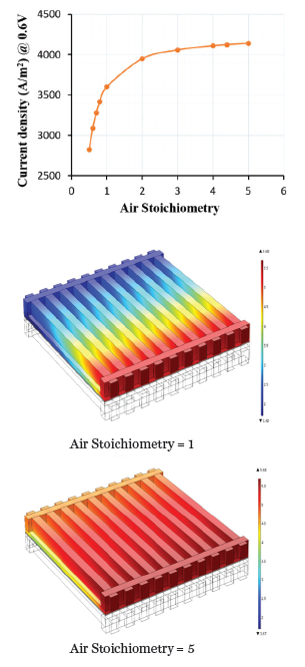 Figure 4. Plots of the current density produced by the fuel cell for different air stoichiometries. An air-to-fuel ratio of 5 resulted in greater and more consistent current output.
The effect of stoichiometry — the ratio between the actual inflow of reactant gases and the amount required for producing a given amount of power — is shown in Figure 4 for a parallel flow field. Lele’s team studied different flow field types to determine the most effective shape and layout for the flow channels. “We were interested in analyzing the four known principle types of flow fields: parallel, serpentine, pin, and interdigitated,” he continues. “Using COMSOL, we found that the last of these [interdigitated] had certain advantages that could be exploited for high-temperature PEM fuel cells.”
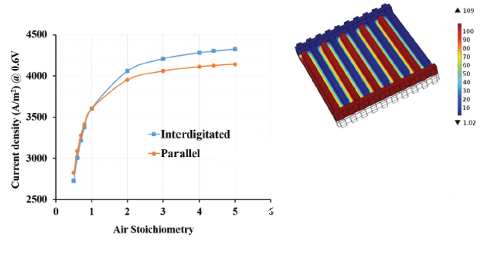 Figure 5. Left: Comparison of the average current density delivered by the fuel cell as a function of air stoichiometry for interdigitated and parallel flow designs. Right: Fluid pressure in microchannels with the interdigitated flow design.
Comparisons of the current density resulting from different flow shapes confirmed that the interdigitated flow type was preferable (Figure 5). More specifically, the faster reaction rate occurring with the interdigitated flow field is a consequence of pressure-driven convective mass transport in the GDL and electrode, which is absent in the other three flow types. Faster reaction rates occurring with the interdigitated type lead to better efficiency and more hydrogen and
oxygen being used up in the reactions. The pressure profile (Figure 5) clearly reveals the possibility of convection within the GDL due to a pressure drop between two consecutive channels.
MOVING TOWARD GREENER FUEL
Analyzing the PEM fuel cell configuration in COMSOL allowed the team to choose the right flow pattern, carbon fiber layer, and gas input levels to maximize the power output. “COMSOL has helped us to look at the influence of all these variables on the final output,” Lele concludes. “Once you run the sensitivity analysis, you can figure out which variables are most important.”
As they move toward licensing and mass production of the PEM fuel cells for power generation, the researchers at NCL look forward to seeing India’s telecom towers run more cleanly and reliably. In the future, they expect these advancements to help the whole country move toward greener fuel for powering other structures, such as buildings and transportation networks.
VIRTUALLY INVESTIGATE THE CHARACTERISTICS OF YOUR SYSTEM WITH EISANALYSIS
By ED FONTES
The principle of EIS is quite simple. An average voltage (V0) is applied with a small sinusoidal perturbation over time. As a consequence, a corresponding sinusoidal current is obtained as a response to the voltage perturbations (see the figure below).
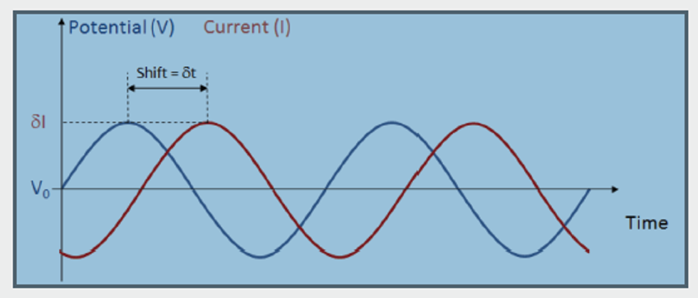
The current response may have a shift in time (δt) compared to the voltage. A shift can be caused by processes that delay the response of the current to the sinusoidal perturbation in voltage. For example, at low frequencies, slow processes such as mass transport may be responsible for such a shift while fast processes may be able to perfectly “follow” the voltage perturbations. At high frequencies, slow processes will only “see” the average voltage; they will not be able to respond to the voltage perturbations. Instead, fast processes, such as the reaction kinetics, will be responsible for the shift in the response at high frequencies. Additionally, the amplitude of the response (δI) may vary at different frequencies.
By sweeping over different frequencies, the method is able to separate processes with different time constants. The time shift and the current response’s amplitude to the voltage perturbation are reflected in the complex impedance, where a shift in time can be represented in the imaginary part of the impedance and the absolute value of the impedance explains the proportionality of the response.
The impedance response gives insight into several fuel cell properties and processes. At high frequencies, short time-scale processes such as capacitance, electrochemical reactions, and local resistances affect the impedance. On the other hand, at low frequencies, phenomena such as the diffusion in the pore electrolyte contribute to the impedance. Frequency sweeps can be carried out at different polarizations of the fuel cell to investigate phenomena at different loads. The combination of modeling EIS and parameter estimation with experimental data can then provide accurate descriptions of transport and reaction properties during operation at different loads.
Click here to read the 2017 edition of Multiphysics Simulation and learn how mathematical modeling and multiphysics simulation are being leveraged as a powerful tool in many other industries.