The BBC micro:bit makes for an effective digital timer. Here's how to turn your micro:bit into a timer for sports, gaming, cooking, or any of your other needs.
December 10, 2019

Timed activities such as sports, gaming, and cooking are monitored and alerted with digital timers. A digital timer uses an electronic counter circuit to keep track of timed events or activities based on preset and an accumulated- values being equal. The preset value can be set using either a rotary based control, a keypad, or discrete tactile pushbuttons. After the preset value has been set, the electronic counter will then accumulate time, thereby creating a predetermined delay in the timer.
Upon the accumulated value reaching the preset time value, the digital timer will trigger an output wired circuit. Traditionally, a transistor Open Collector (O.C) is used to drive an electromechanical relay. The electromechanical relay can control an electrical load wired to its switching contacts. Also, a digital display such as a seven segment LED or LCD can be used to show the digital counters’ pulses.
|
A digital timer circuit using discrete Transistor-Transistor-Logic (TTL) integrated circuits (ICs) and electrical-electronic components. (Image source: Don Wilcher) |
A typical digital timer
Besides digital timers being deployed in consumer application-based activities, these programmable devices are found in manufacturing facilities. For small industrial control applications such as operating electropneumatic, electrohydraulic circuits or running parts conveyors, digital timers can be implemented quite easily. The preset value is traditionally set using a pair of discrete tactile pushbutton switches. The tactile pushbutton switches allow the operator to change the preset value. The time can be adjusted for an up or down count trigger setting. Once set, the internal electronic counter will proceed to count based on the time adjusted by the operator using the tactile pushbutton switches.
A digital timer can be easily constructed using a few off the shelf components. A typical digital timer has several digital and analog circuits for setting the preset value and displaying the time.
This timer’s, output control, and display functions can be implemented using a BBC micro:bit and an electromechanical relay.
The BBC micro:bit Specs
The BBC micro:bit is a small embedded platform that allows a variety of smart electronic devices to be created by makers, educators, hobbyists, and engineers. The electronics prototyping platform is engineered to be programmed in a variety of coding languages like Javascript, MicroPython, CircuitPython, or Google Blockly code.
Several external electrical and electronics devices and circuits can be attached to the micro:bit using an etched printed circuit board (PCB) edge connector. At the heart of the micro:bit is a Nordic Semiconductor nRF51822 system on a chip (SoC) integrated circuit (IC). The nRF51822 SoC IC is a low power device operating at +3.3V direct current (DC) supply voltage. Included within the SoC is a 2.4GHz transceiver and a 32bit ARM Cortex M0 central processing unit (CPU) with an integrated temperature sensor. Also, flash memory, Bluetooth low energy (BLE), an accelerometer, analog, and digital circuit peripherals support the micro:bit. In addition, the micro:bit uses a 5x5 array of discrete LEDs to display text messages, images, and numerical values.
|
The BBC micro:bit is populated with a nRF51822 SoC and supported by analog and digital electronic circuits. (Image source: BBC micro:bit) |
The micro:bit Digital Timer Build
To build a digital timer using the micro:bit basically requires four building block components: the digital timer code, a micro:bit, a transistor relay driver circuit, and an electromechanical relay.
|
A system block diagram for a micro:bit Digital Timer. (Image source: Don Wilcher) |
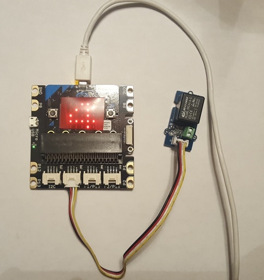
A solderless breadboard can be used to wire three of the four building block components together. Also, the discrete electromechanical relay and transistor relay driver component circuits can be wire on a solderless breadboard. Although this method of construction is okay, another approach is to insert the micro:bit into an interface board which provides four input/output connectors, a +3.3VDC supply, and ground. The transistor relay driver and electromechanical relay can be purchased as a single module. Both circuit components are conveniently populated on one PCB. A small jumper harness is attached from the interface board to the transistor driven relay board making the electrical interface between the micro:bit and the electromechanical relay circuit conveniently easy.
|
The micro: bit attached to the transistor driven relay board with a mini jumper harness. (Image source: Don Wilcher) |
The two tactile pushbuttons allow the digital timer’s preset time to be adjusted using button A on the micro:bit. Locking in the preset time is accomplished using the B button. Pressing both the A and B buttons together will start the count-down timing sequence.
|
Setting the preset time on the micro:bit Digital Timer. (Image source: Don Wilcher) |
The digital timer function can be coded using Javascript or Google’s Blockly Code. Also, prior to downloading the code to the physical micro:bit the software can be tested using the Microsoft Makecode micro:bit simulator. Such a debug feature will capture software function glitches and errors prior to deploying the code on the physical device.
|
The micro:bit Digital Timer Blockly Code. (Image source: Don Wilcher) |
|
The Javascript micro:bit Digital Timer code. (Image source: Don Wilcher) |
|
Code testing on the Microsoft micro:bit Makecode simulator. (Image source: Don Wilcher) |
After the displayed count-down value reaches zero, the message Device ON will scroll across the discrete LED display.
Various electrical devices like DC voltage small electric motors and electronic devices can be operated using this simple but effective digital timer. Additional information on the micro:bit can be found on the following website. The Microsoft Makecode programming environment can be found on its website as well.
RELATED ARTICLES:
Don is a passionate teacher of electronics technology and an electrical engineer with 26 years of industrial experience. He has worked on industrial robotics systems, automotive electronic modules and systems, and embedded wireless controls for small consumer appliances. He's currently developing 21st century educational products focusing on the Internet of Things for makers, engineers, technicians, and educators. He is also a Certified Electronics Technician with ETA International and a book author.
About the Author(s)
You May Also Like


