
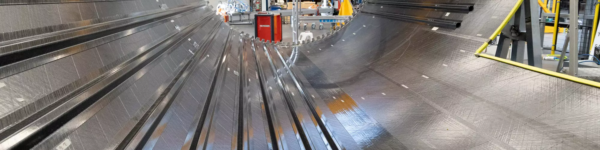


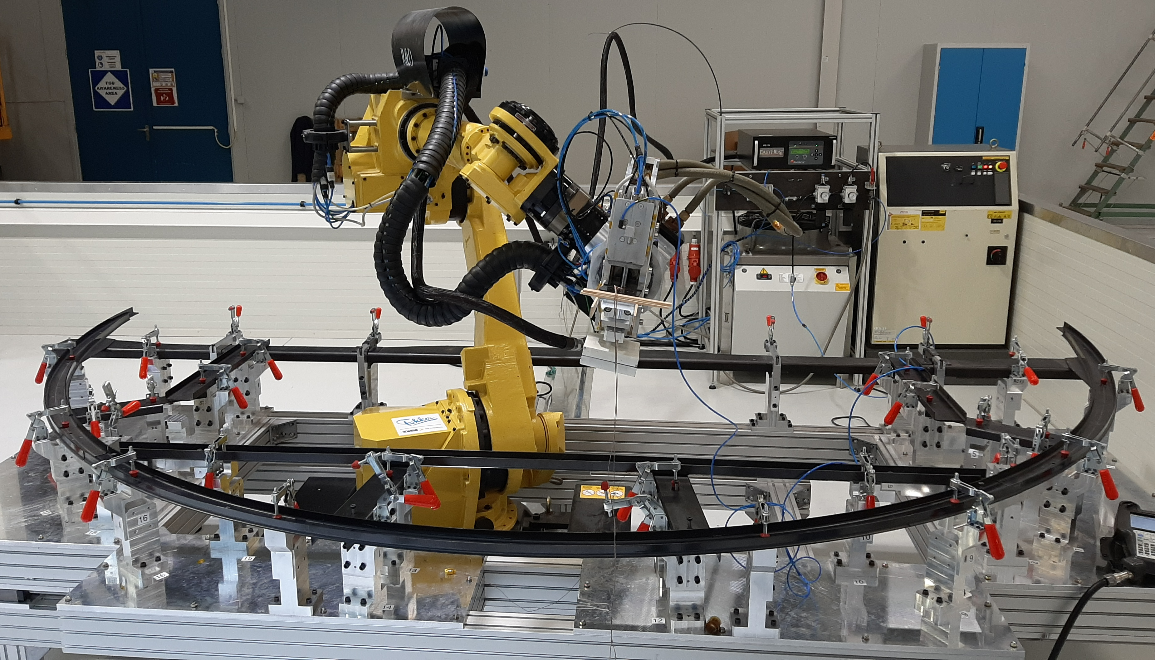
The lower fuselage half of the Multifunctional Fuselage Demonstrator (MFFD) being assembled at SAM|XL, shown here with conduction-welded stringers and ultrasonic spot-welded clips. Photo Credit: SAM|XL
Landscape photo at top: MFFD being assembled at SAM|XL with ultrasonically tack-welded stringers ready to be conduction welded. Photo Credit: SAM|XL
This is Part 2 of CW’s October 2022 feature: “Thermoplastic composites welding advances for more sustainable airframes”. Here, discussion continues regarding the latest developments across multiple welding techniques and demonstrators, with a detailed look at process control, certification and other challenges that are being overcome in order to mature dustless, fastener-less composites for future airframes. This discussion is also a good review of the numerous factors involved in producing a good-quality weld and how quality assurance might be facilitated by digital twins and artificial intelligence (AI). For details about the various processes and demonstrators, see Part 1 at the link above.
Process control, sensors, NDT
What parameters are important to monitor and/or control to ensure a good weld?


Ultrasonic spot welding: For ultrasonic spot welding in the lower half of the Multifunctional Fuselage Demonstrator (MFFD), SAM|XL (Delft, Netherlands) mostly uses time control and monitors the power, consumed energy and vertical sonotrode displacement (i.e., depth of welding) during the welding process, says Bram Jongbloed, materials and process engineer at SAM|XL. “We also use force indicators to monitor the welding and consolidation force. There are many things that you can potentially monitor during the welding process — such as vibration frequency and temperature — by the use of thermocouples. Our research partners from the Delft University of technology (TU Delft, Netherlands) can then study these in an AI model to see how to control the ultrasonic spot-welding process using a closed-loop control system, based on input from various parameters.”
Continuous ultrasonic welding at DLR: “This process control at SAM|XL is also true for DLR’s continuous ultrasonic welding process, were we monitor all parameters from the generator (i.e. amplitude, frequency over time), as well as the travel speed from the robot and the forces applied to the horn and consolidation unit,” says Frederic Fischer, technical lead for thermoplastic composites production at the DLR Center for Lightweight Production Technology (ZLP, Augsburg, Germay). “Especially during run-in and run-out [the beginning and end of the continuous weld], we actively control the amplitude levels. Most importantly, however, displacement of the end-effector from the predefined path due to process forces are compensated by a camera-based path correction, detecting the stringer edge at a holding accuracy of ≤ 0.1 millimeter.”
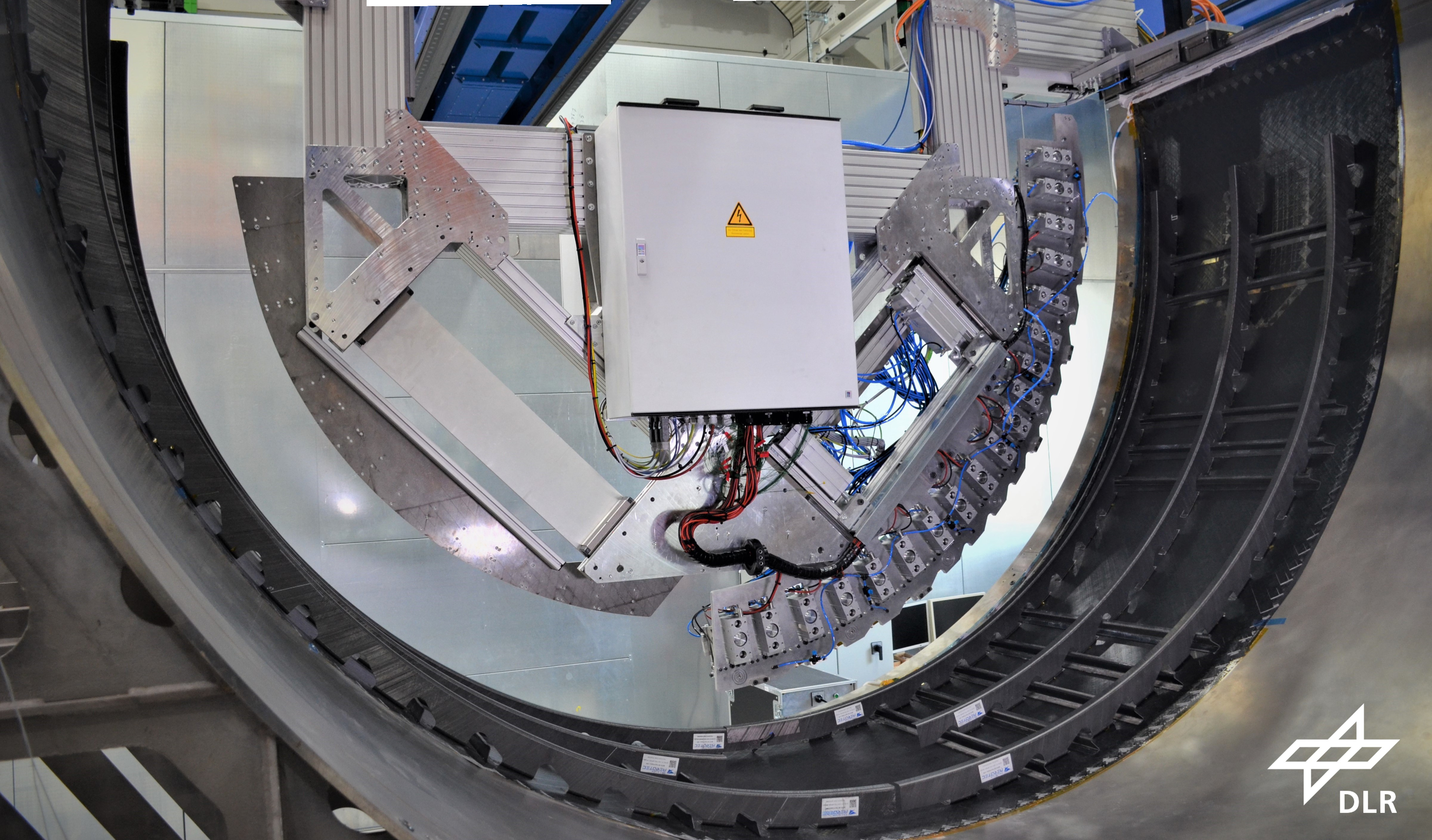
DLR resistance welding the test shell for the upper half fuselage of the MFFD. The curved welding bridge comprises numerous modules. Each applies pressure via a pneumatic cylinder and heating via resistance from applied current/voltage. Photo Credit: DLR Institute of Structures and Design and ZLP Augsburg
Resistance welding: Fischer also describes process control for resistance welding used in the upper fuselage of the MFFD. “We measure the resistance of the welding element via the current and applied voltage, which gives us the energy,” he explains. “With this we can run a very controlled process based on the defined optimum parameters for the specific part. We don’t need additional sensors for control loops, but we do measure the pressure from the welding bridge cylinders to make sure that it is constant.”
“Sensors are important during upscaling of the process,” notes Michael Kupke, vice director, DLR Institute of Structures and Design and head of department at ZLP. “For example, we place thermocouples in the weld interface, and there is indeed a lot of measurement and work in defining the optimum process. After that, you’re simply monitoring conformity to your specification. For industrialization, you want the process to be as simple as possible. You don’t want to be messing with sensors in every weldline.”
ISW induction welding: The ISW process uses a mobile susceptor that moves with the weld head. “We monitor the weld head speed and temperature in the part surface and metal susceptor using an infrared pyrometer and an infrared [IR] camera,” says Jérôme Raynal, aeronautics & composites director for IS Groupe (Villepint, France). “Because the susceptor creates the melt at the weld interface, we can monitor and control that directly. This also allows us to evaluate the homogeneity of the susceptor itself. We are using a pneumatic jack to control and manage pressure applied on the welding and cooling area.”
Induction welding and IR camera-based control:
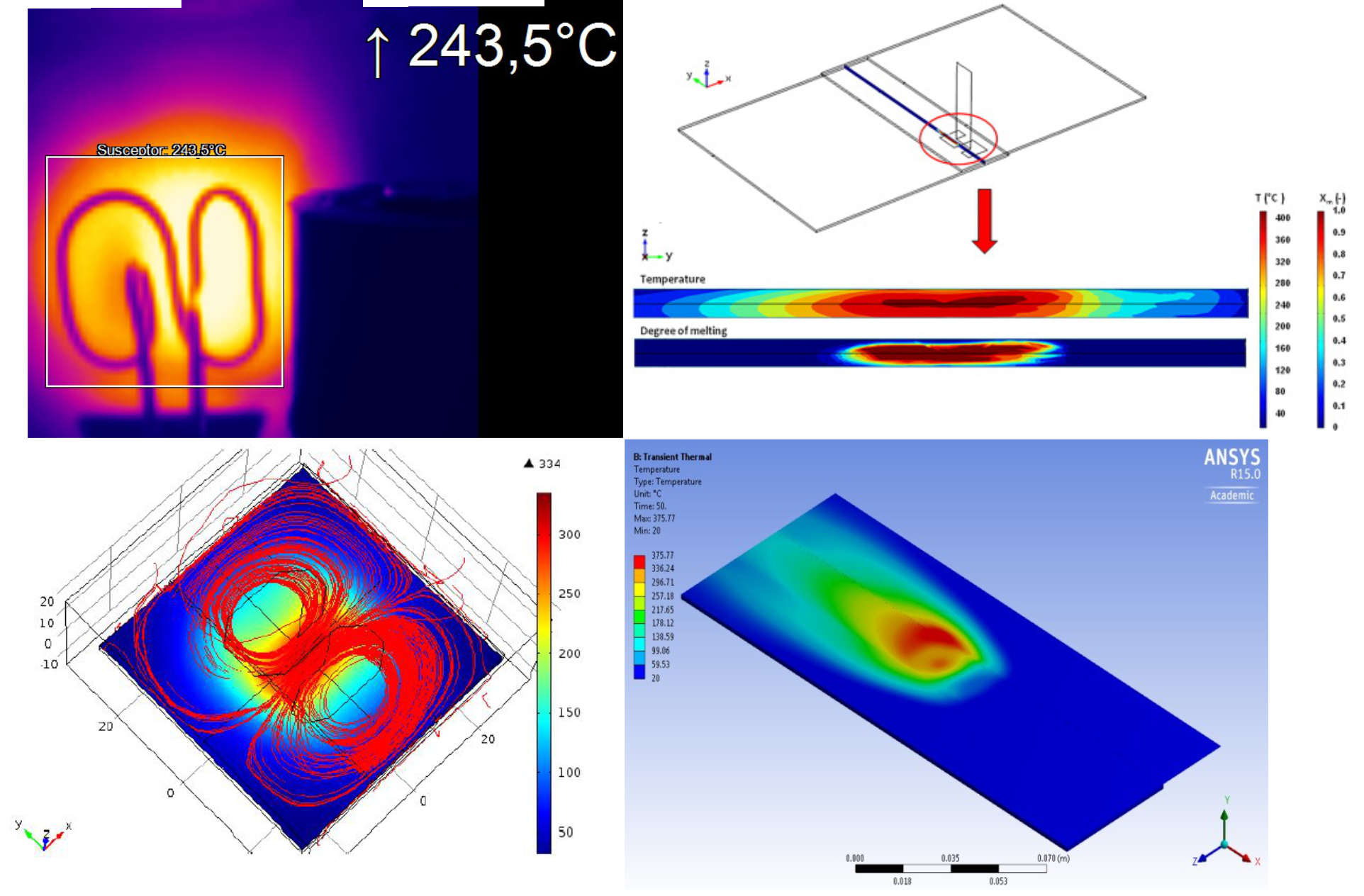
CETMA has integrated a thermal camera to monitor its induction welding process (top left) and performs various process simulations — including induced eddy currents (bottom left), temperature distribution (bottom right) and degree of melt in the weldline (top right). The models for these simulations use input data including material properties such as relative permeability, specific heat, relative permittivity, density, emissivity, resistivity and thermal conductivity. Photo Credit: CETMA
Integration of a thermal camera to replace the previous pyrometer was an important upgrade to CETMA’s (Brindisi, Italy) induction welding system, says Giuseppe Buccoliero, advanced materials and process development engineer at CETMA. “This enabled monitoring larger areas (5 x 5 centimeters) of the part surface.” For one of the DEWTECOMP project demonstrators, the weld area being heated was 20 millimeters long x 25 millimeters wide. “Induction welding is very efficient in heating but is challenging to control the temperature,” he continues. “To do this, you need to know the point of maximum temperature during the process. Otherwise, you risk overheating the matrix. The [IR] camera’s large monitoring area helps us find the hottest point. We then correlate this to the weld temperature and use that to regulate the power to maintain constant temperature.”
“To make sure heat is concentrated at the weld interface,” he continues, “we first optimize the process using thermocouples placed at the interface and on the part surface to correlate and validate the IR camera readings. For example, the weld interface is at 380°C while the surface is at 250°C. The camera is directly connected to the induction welding generator, so it controls the power. The surface temperature is a key parameter that you set in the system HMI. The thermal camera then checks to keep the surface temperature at that setting and the weld interface above the melt temperature.”
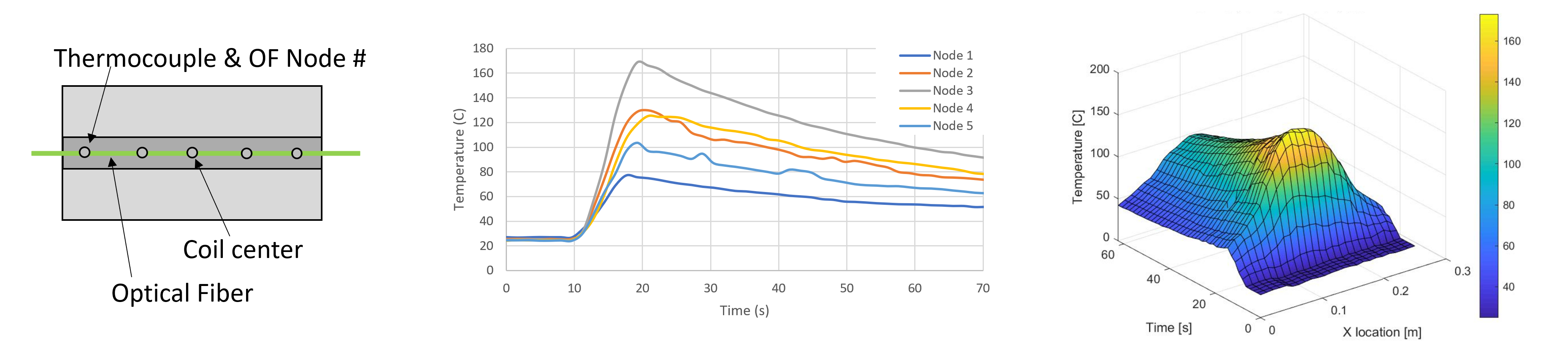
Raytheon Technologies conduction induction welding trials on curved panels using a robotic system and optical fibers in the weldline (above, left) that showed the 2D and 3D temperature distributions above (center and right). Photo Credit: Raytheon Technologies Research Center
Optical fibers and IR camera: “We demonstrated optical fiber temperature sensing at the coupon level,” says Dr. Wenping Zhao at Raytheon Technologies Research Center (East Hartford, Conn., U.S.), describing his work with the University of South Carolina (Columbia, S.C., U.S.) team led by Dr. Wout De Backer. “It showed great potential for thermoplastic composites weldline temperature sensing without having significant detrimental effect on the weld. We plan to scale up the use of optical fiber sensors in our future welding development.” The induction welding trials completed also used thermocouples and an IR camera. “Thermocouples embedded at the weldline are fine for welding technology development, but in applications, they will likely be placed away from the weldine and used in combination with an IR camera and simulation to serve as indirect temperature measurement during welding.”
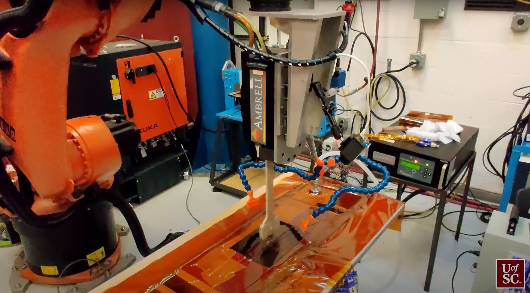
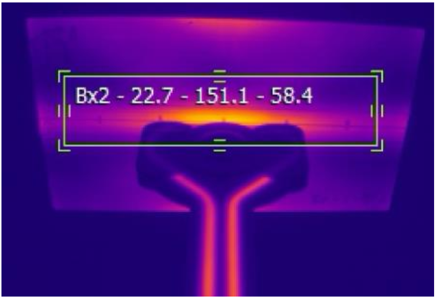
This infrared (IR) camera image (bottom) of a weldline was taken during an induction welding trial (top). The IR camera is the small black box to the right and bottom of the welding head. The induction coil projects down from the welding head toward the composite panel. The blue tube seen on either side of the IR camera is used for forced air cooling of the weld surface. Photo Credit: University of South Carolina
“The IR camera was mounted to the robot welding head, which also holds the induction coil,” says De Backer. “The camera was positioned such that most of the weldline is not obstructed. For the type of welds we were doing, the heating profile was symmetric with respect to the plane of the induction coil. Thus, as long as we could see half of the welding area, we had enough information about the material’s response.”
De Backer notes that the University of South Carolina team is also involved in the HICAM (Hi-Rate Composite Aircraft Manufacturing) project (2021-2027), part of NASA’s Sustainable Flight National Partnership. Similar to the goals for the MFFD, HICAM’s goals, as described in an online presentation, include to enable production of 60-80 aircraft/month, reduce cost by 30-50% and incur no weight penalty versus a baseline of Boeing 787/777x composite aircraft production in 2020. De Backer says that induction welding is one of many thermoplastic joining technologies under evaluation for use in HICAM, that is, if thermoplastic composites are indeed selected for the planned full-scale airframe component demonstrators to be completed by 2026, aimed to achieve technology readiness level 6.
Weld speed vs. crystallization: “Obviously, there is a temperature gradient along the weldline as the induction coil passes,” says Buccoliero at CETMA. “And there is a roller that applies the necessary pressure. So, another parameter you must optimize is the weld head speed, because the roller must pass while the weldline is above the crystallization temperature in order to have a good interdiffusion between the two components being welded. If you pass with the roller when the matrix is already cooled and crystalline, you cannot obtain the joint strength between the parts. Another important optimization is to obtain the maximum crystallization content of the material so that you optimize the mechanical properties of the joint. Otherwise, you risk an amorphous phase that reduces the weld properties. We verified this by DSC (dynamic scanning calorimetry) analysis before and after welding to check that the crystallinity was the same as the maximum of the base material.”
Sensors and NDT: “For our KVE INDUCT process,” explains Maarten Bach, thermoplastics account manager at KVE Composites (The Hague, Netherlands), “we control the welding current, pressure and induction coil speed, and measure the weld interface temperature as a main process parameter.” KVE, working with parent company and Tier 1 airframer Daher Aerospace (Paris, France), use thermocouples as well as optical fibers to complete process calibrations in advance, but these won’t be embedded in actual serial parts. “We optimize the process parameters and then we monitor during production to make sure we’re conforming to the spec,” says Dominique Bailly, Daher VP of R&D, noting this is how Daher certifies the stamped thermoplastic parts it produces. “We also test with NDT. This is standard today — all parts manufacturers and OEMs use statistical process control with NDT of produced parts — typically using ultrasonic inspection. However, ultrasound is not enough. We are testing other technologies in our development programs with various partners.”
The following discussion is edited from CW’s June 2021 webinar on induction welding. “We are performing ultrasonic inspection,” says Raynal at IS Groupe. “We consider the part not acceptable if the ‘loss of intensity’ of the ultrasound signal is over 6db, which is standard in aeronautics.”
Floor beam (top) and fuselage frame (center) subassemblies for the MFFD lower half fuselage are conduction welded together in this welding cell (bottom) at the GKN Aerospace Global Tech Center – NL facility (Hoogeveen, Netherlands). The end effector completes 60x18 millimeter welds and will also be used later to weld the completed floor beam grid to the fuselage clips already integrated at SAM|XL (see image at top). Photo Credit: GKN Fokker
Leo Muijs, chief technologist at Tier 1 airframer GKN Aerospace (Redditch, U.K.), says that GKN Fokker (Hoogeveen, Netherlands) is using pulse-echo ultrasonic inspection of its welded structures, noting, “We are looking at other non-contact methods for large areas in order to meet higher volume requirements from our customer.”
Simon Maire-Vigueur, head of R&T composites manufacturing for Airbus Atlantic (Toulouse, France), pointed out that with classical C-scan and ultrasonic testing, “I’m not able to detect gaps in the weld, so we have to work on new inspection technologies to detect this and certify good welds.”
Bach at KVE Composites does not fully agree, but says that for most of their welds, there is a 100% correlation between good/not good microscopy with good/not good NDI. “The challenge is at locations where laminate surfaces are not parallel, including joggles and ply dropoffs, where conventional ultrasonic inspection is challenging. So, we are working on a combination of new NDT methods, process monitoring and in-situ process control using a digital twin of the welding process. We’ve seen at KVE that a good weld has nearly the same mechanical properties as the base laminate. But we’ve also seen sections with a limited amount of fusion between the two laminates, yet NDT didn’t detect it. There seems to be a threshold temperature and weld time which you need to reach, in order to get to the desired mechanical properties. So, you must have process control but also ensure that the pressure and temperature have been correct throughout the weld.”
Dielectric sensors for welding
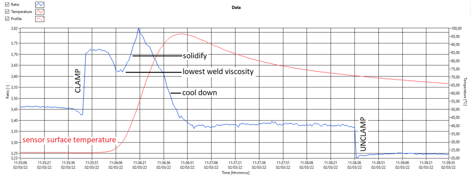
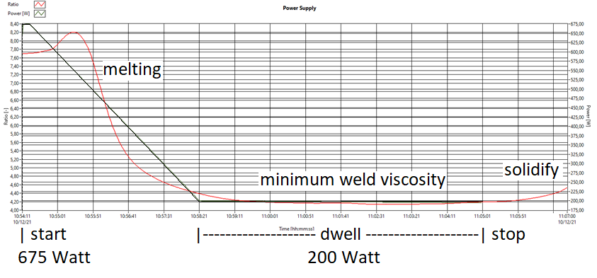
Twenco DEA sensor data. Induction welding trial graph (top) of temperature (red) vs. ratio of received/transmitted RF signal (blue). Resistance welding trial graph (bottom) of viscosity (red) vs. power (black), showing stable viscosity during hold at constant low power. Photo Credit: “Twenco develops sensors for smart molds and process control in resin infusion and composites welding”
Twenco (Vriezenveen, Netherlands) has also demonstrated its NDT dielectric analyzer in resistance and induction welding trials, the latter using a KVE welding test setup. Twenco’s sensor is a noninvasive dielectric sensor that uses voltage and radio frequency (RF) signals to monitor the composite’s material state during processing. In both trials, sensors were placed on the top surface of the top plate in the weld. For induction welding, says company founder, Cor Boksem, “the Twenco sensor provided visibility into what was happening inside the weld, and you can see that the maximum melting was stable for five seconds. With a few tests, you could easily characterize the relationship between weld power and travel speed to help optimize the welding process.” For resistance welding, Twenco studied the possibility to reduce energy usage. “We started with 100% power using 675 watts and decreased that to 200 watts,” says Boksem. “We could see that we were still able to melt the resin and hold it exactly stable. And now, instead of doing this manually, we could do it automatically by developing an algorithm based on the viscosity curve.”
AI-based process control, digital twin
New sensors like Twenco’s may have a place in future welding control systems. SAM|XL CEO, Kjelt van Rijswijk, notes that the ultrasonic welder system at SAM|XL is fairly open with room for many kinds of sensors that can be used to monitor speed, temperature and position. “You want to be able to simultaneously control the welding tool and the position of the robot. However, there is no ‘one size fits all’ — what you do depends on the type and size of the part, materials, welding access and the welding process. For example, induction welding is typically a more closed system, making it more complex to introduce external sensors to monitor the welding process and its quality. Therefore, it needs AI to make the identification of suitable process specs shorter.”

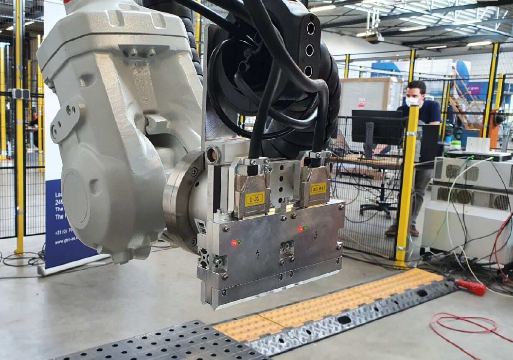
Position control of ultrasonic spot welder for welding of clips to lower half of MFFD fuselage. Photo Credit: SAM|XL
SAM|XL is working with KVE and Daher, developing how to place sensors in a smart way to industrialize robotic induction welding. “We’re also developing technologies to foolproof and industrialize continuous ultrasonic welding,” says Jongbloed, “including monitoring systems that use AI to certify process parameters and link these to weld quality to create a closed-loop control system.” This is multi-year roadmap, says Van Rijswijk, “and we are just in the beginning phases, but it will allow us to weld very large structures reliably and efficiently. These projects with our partners will also demonstrate the business case for welded composites structures, including which welding technology is best for which applications.”
SAM|XL’s technology agnosticism is interesting because it drives a different solution to bespoke qualification and control. For example, during process specification for welding the MFFD upper fuselage, Kupke noted that DLR tested hundreds of coupons. This is also required for induction welding because the heat generated is so dependent on each material’s electromagnetic and heating behavior as well as each part’s geometry. “What we’re developing is an AI-enabled automated solution,” says Van Rijswijk. “When I weld, I want to use robots that can see where the two parts are overlapping so it can teach itself what to do. I don’t want to manually teach the robot each time I weld. Laser distance sensors can monitor the weld head position and distancing from the weldline. These and other sensors allow the robot to see what needs to be done and program itself, and then to monitor the material conversion. NDT sensors can then look internally and check consolidation. Thus, there is no endless programming, no trial and error — you simply put two panels together, press start, and the robotic system welds them with monitoring and NDT done automatically.”
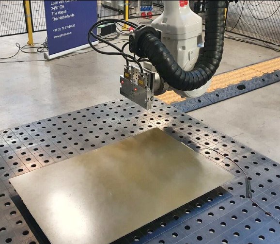
SAM|XL is developing autonomous, non-contact NDT of composite structures. Photo Credit: SAM|XL
Van Rijswijk notes that contactless sensors are ideal for this type of robotization. “Together with TNO [Netherlands applied research organization], we are developing contactless NDT,” he explains, “where you place a panel on our gantry system, the robot takes images and then programs itself, executing NDT without any manual programming. This is a technology strain that is running in parallel with our welding R&D and we will eventually integrate them.” He notes that digital transformation takes time. “It’s about setting up our hardware and software platforms in such a way that you can add to and build onto them. You need to be able to continuously improve your processes but also the equipment to do those processes.”
Maarten Labordus, R&D manager at KVE Composites, believes that simulation and modeling are also key in the industrialization of induction welding. “KVE is using two approaches,” he explains. “One is traditional bottom-up modeling, using commercially available software and special heat and electrical conductivity measuring equipment to make input data as accurate as possible. The other is a top-down approach that uses a set of best guesses as input and then calibrates the model with thermal data from welding experiments with realistic boundary conditions. This work is being done in cooperation with ESI Group (Rungis, France) in the PENELOPE project.”
ESI follows a multi-step approach in their simulation, says Labordus, “by first doing a very elaborate electromagnetic and thermal analysis. This analysis can take up to several days, followed by a calibration based on KVE’s measured thermal data. ESI then distills a so-called heat source function, which can be used to perform very fast simulations. Currently, KVE and ESI are finalizing their modeling activities and moving toward development of an actual digital twin of the induction welding process, which will then be implemented in an inline process control for KVE’s welding systems using non-invasive thermal sensors embedded in the weld tooling.”
Certification, crack arresters
The issue of certification was debated during a panel discussion titled, “Advancements in Thermoplastic Bonding and Joining” at the March 2022 Thermoplastic Composites Conference (San Diego, Calif., U.S.). One assertion made during the discussion was that welded metal joints are one reason why NDT became an industry in the first place, says panel participant Waruna Seneviratne, director of the Advanced Technologies Lab for Aerospace Systems (ATLAS) at Wichita State University’s National Institute for Aviation Research (NIAR, Wichita, Kan., U.S.). “My view is that you basically have three approaches for certification of bonded or welded joints: proof testing of each production article to limit load, full NDI to detect defects beyond an allowable threshold or some sort of crack arrest features. This would be in addition to conducting a rigorous bond process qualification and implementing quality controls.”
“With bonding, you have the possibility of contamination in the bondline or a kissing bond, every single time,” contends Michael Hugon, intellectual property manager at Daher. “So, you could have adhesive failure. We shouldn’t have this issue in welding because we are remelting the surface of both parts and diffusing those into each other so that there is no longer an interface. I also lead a project in friction stir welding (FSW) of metals, where you diffuse the materials of each part to make one part. You no longer keep a solid interface, so you’re not sensitive to potential contamination. In thermoplastic composites, we are also heating above the Tg [glass transition temperature] in the weldline.” Thus, TP welding should be similar to thermoset co-curing, notes Bailly, “where you don’t make any differentiation in the subparts — they have been integrated into a single part.”
“People get excited about using chicken rivets in bonded joints,” says Seneviratne, “but they are essentially crack arrest features that contain potential damage growth beyond a safe limit. In the case of bond failure in a wing, for example, crack arrest features allow the pilot to land the airplane. And I’m sure that critical thermoplastic welded joints that are flying today have some sort of a crack arrest features to prevent catastrophic failure or complete joint failure in the event of damage growth.”
Muijs admits that the welded rudders and the control surfaces GKN Fokker has made for Gulfstream and Dassault aircraft still look like a traditional assembly with a lot of fasteners. “As in metal bonded structures, we use disbond arrest features to prevent peeling in the welds. In the MFFD, however, there is a lot of welding and only a few crack arresters.”
Refill friction stir spot welding (FSSW)
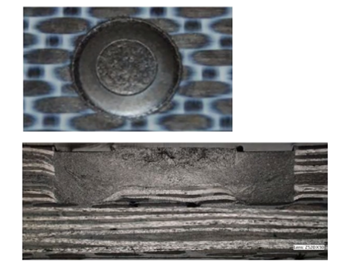
Top view (top) and cross-section (bottom) of a CF/thermoplastic refill FSSW joint. Photo Credit: Helmholtz Zentrum Hereon
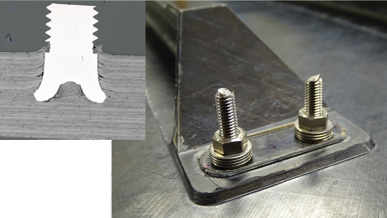
Friction riveting of stringer runout.
Photo Credit: Clean Sky 2 TORNADO project, GKN Fokker.
“For many years now,” he continues, “I have been trying to develop other concepts which better suit thermoplastic composites. It makes no sense to have a nice process like welding and then drill holes that ruin the whole concept. So, in the MFFD subproject TORNADO, we are working with the University of Patras in Greece and with KVE to use refill friction stir spot welding (FSSW). As in normal FSSW, we melt the material already there and then refill it using the same material. Another concept is friction riveting, where we use a rivet designed so that when it enters the material, using a specific speed and force, it forms a head to prevent pull out. And then on top you can place a nut to hold it in position. “We’re making progress,” he adds. “We won’t use these in the MFFD, but we will make test panels and separate demonstrations.”
Surface preparation
Even with crack arresters, Seneviratne still sees issues with surface contamination and preparation in welding, just as in adhesive bonding. “Many people think that for welded joints, contaminants are not a big issue because you're going to 300 or 400 degrees C, and thus, all of these contaminants get burnt away. But we've done work on contaminants and that’s not true. You must ensure that your surfaces are clean and that you have intimate contact in the interface. People want to use the same surface prep techniques as we’ve done with thermosets, but that doesn't work very well — especially the use of abrasive techniques — for thermoplastic welds.”
GKN Fokker has also researched this. “In our production of wing leading edges and control surfaces, rib flanges are welded to skins,” says longtime thermoplastic composites and welding champion Arnt Offringa, director of the GKN Aerospace Global Technology Centre (GTC, Hoogeveen, Netherlands). “Ribs are first stamp formed from laminates. Because of this manufacturing process, rib flanges are not 100% clean. That’s why we do Scotch-Brite cleaning of flanges, followed by an alcohol wipe. For the skins, we use only an alcohol wipe. In order to ascertain the effect of someone touching the parts to be joined before welding, we researched the effect of finger grease on weld quality. There was no effect. When our welded joints are pulled apart in testing, they consistently show a good failure in the sense failure occurs in one of the parts, not in the weld area.” Offringa notes that this surface treatment is much simpler than for bonded primary structures, “where you have to make sure that your surfaces are very, very clean.”
“We saw that using energetic methods such as atmospheric plasma treatment significantly improved the mechanical properties of thermoplastic bonded joints,” says Seneviratne, “and resulted in acceptable failure modes away from the weld interface. However, it was not that significant for welded joints. Still, surface cleanliness is important prior to bond or weld, and we’ve seen that atmospheric plasma is the best way to do that, especially for welds. However, unlike for bonded joints, the surface preparation is not crucial in welds, but other process parameters — such as thermal management, tooling for maintaining consolidation pressure in the weld surfaces while above melt temperature and time under these conditions — are critical. Thus, as a community, we need to establish weld process qualification protocols and the means of compliance to ensure safe operation throughout the design life of the joint.”
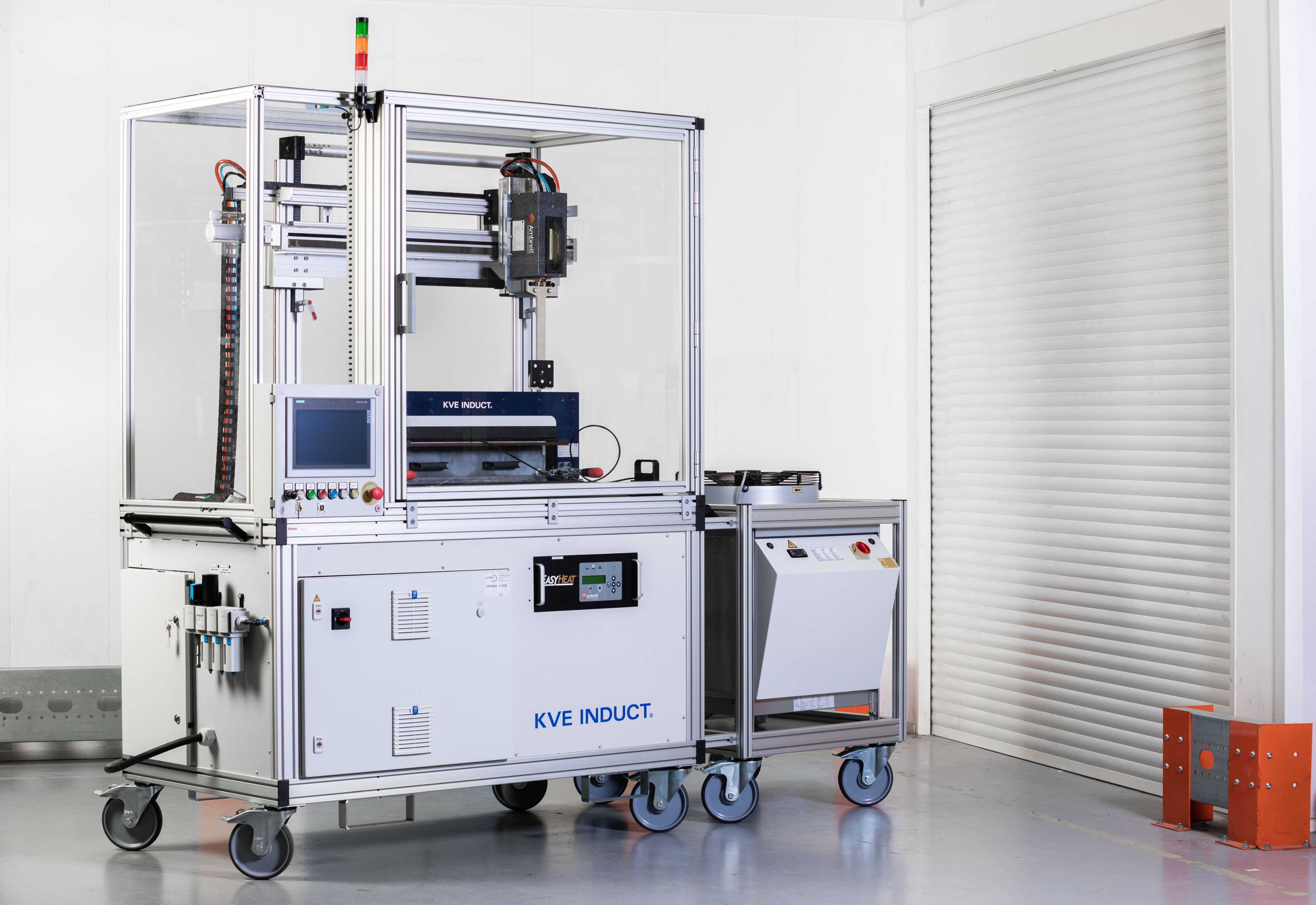

KVE INDUCT welding setup for test coupons (bottom) installed in its commercially available mobile welding system (top). Photo Credit: KVE Composites
“We have found that surface preparation is not critical for induction welding,” says Labordus at KVE. This is based on significant testing KVE and partner Rescoll (Pessac, France) performed in the MECATESTERS subprogram (April 2019-October 2021), which was basically a qualification of CF/LMPAEK unitape for induction welded parts. Tests included single-lap shear (SLS), L-profile pull-off and shear, combinations of peel and shear, GIC static and one million cycle GIIC fatigue, cold (-55°C)/hot (80-120°C) and aging at 90% humidity, plus studies of welding parameters, including upper and lower bounds for temperature and pressure, and the effects of surface contamination and preparation. The latter investigated contamination with three different types of release agents used commonly in press and autoclave processing; specific types of surface preparation including sanding, abrasives and IR treatment; and also the influence of an extra resin film at the interface as well as the fiber orientation here, for example ±45° plies.
“We have found that welded joints are fundamentally different from adhesive bonded joints, since they are not critical to surface treatment and surface condition and should therefore be easier to certify without the use of chicken rivets,” says Labordus. “Still, damage arrest features could further improve the damage tolerance performance of welded joints and speed up acceptance by airworthiness authorities.”
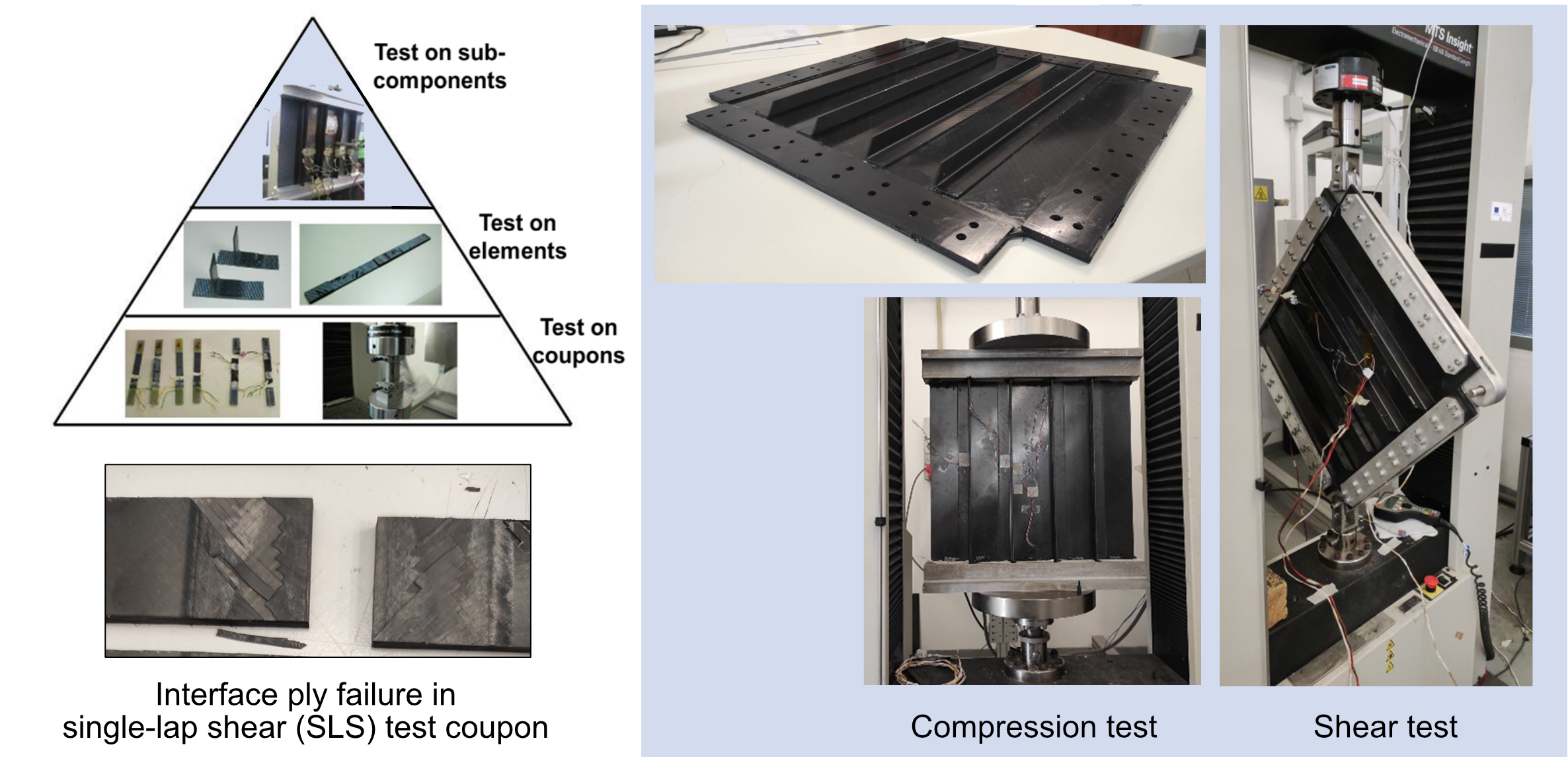
Examples of stepwise, building block approach in testing of induction welded thermoplastic composites. Photo Credit: CETMA
Stepwise Approach
“Similar to bonded joints, applicants for certification of welded joints must develop robust processes as well as rigorous quality control protocols,” says Seneviratne, “and demonstrate the means of compliance to certification authorities using one of the three methods [proof loading, full NDI or crack arresters], or else they must use a completely new certification approach for welds in order to demonstrate durability and damage tolerance. And we should approach this in a stepwise fashion, build up sufficient history with these joints over the years and a lot of data, like what we have done for bonded joints. Eventually, I think we’ll have enough confidence for welded composite primary structures without crack arrest features.”
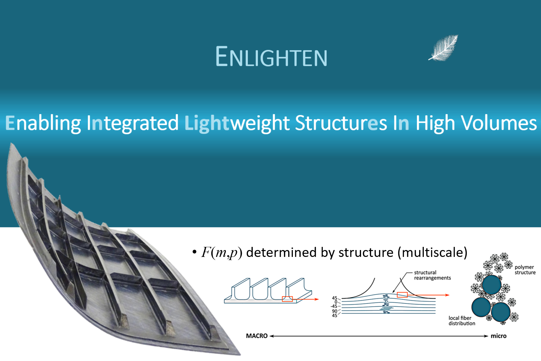
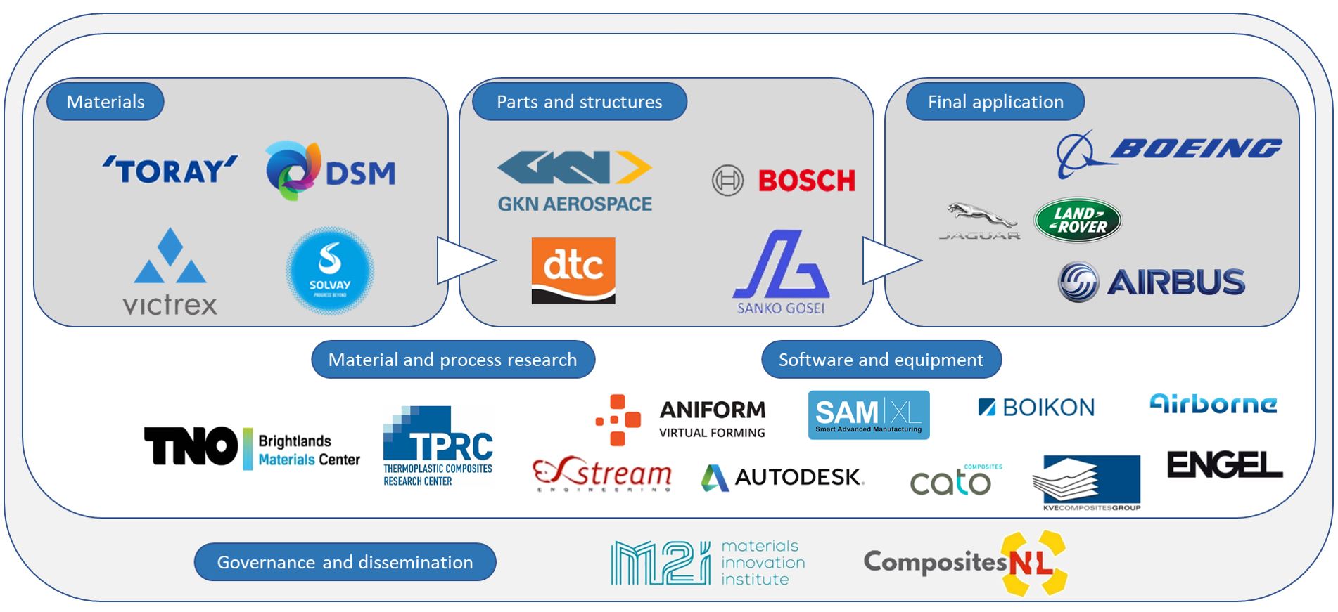
The ENLIGHTEN consortium includes 22 partners and spans both aerospace and automotive supply chains. Photo Credit: “ENLIGHTEN program launched to speed thermoplastic composites industrialization”
That confidence could come fairly soon — at least based on building a lot of data. Indeed, a stepwise approach — i.e., the building block/pyramid of testing first coupons, then sub-elements and then sub-scale and/or full-scale assemblies — has been used by both the upper and lower MFFD fuselage half programs, by IS Groupe and Airbus Atlantic in the ECHOS program and by CETMA for the MFFD door surround (see figure above). And even further data will be added from testing of the MFFD once it is welded in 2023, as well as the TRAMPOLINE project in France, the 5-year, 22-partner ENLIGHTEN project, announced in 2021 and NIAR’s Frankenstein (FS-19) welded demonstrator to be completed by 2025.
Welding widely applied within a decade?
What will it take to have welded UD tape-based thermoplastic composites structures widely used in commercial aircraft? “We need, of course, certification by the aircraft OEMs, and I think this will require NDT that can provide consistent and accurate quality assurance of the welded components,” says Raynal at IS Groupe. “We also need full-size demonstrators that pass all of the required tests, including fatigue.”
“GKN Fokker has been one of the frontrunners with applying thermoplastic composites and also in welded assemblies,” says Bach at KVE. “But the OEMs must also invest in this technology. Over the past two years, we have seen an increasing investment and demand for thermoplastic composites and also for welding. Just looking at the amount of requests that KVE has received, we see that the industry is really looking for this next step in sustainability and the market has started to believe in the applications for thermoplastics and the cost savings possible with welding. We will see more welded thermoplastic composites flying within a decade.”


Related Content

Plant tour: Avel Robotics, Lorient, France
From AFP hydrofoils to more efficient aircraft parts, Avel uses digital design, multiprocess production and a rule-breaking approach for complex 4D composites.
Read More
Long-fiber liquid crystal polymers
High-performance, injection moldable grades to be offered with long glass, carbon fiber options.
Read More
Automated robotic NDT enhances capabilities for composites
Kineco Kaman Composites India uses a bespoke Fill Accubot ultrasonic testing system to boost inspection efficiency and productivity.
Read More
Damage tolerance testing of sandwich composites: The sandwich CAI test
A new ASTM-standardized test method established in 2022 assesses the compression-loaded damage tolerance of sandwich composites.
Read MoreRead Next

CW’s 2024 Top Shops survey offers new approach to benchmarking
Respondents that complete the survey by April 30, 2024, have the chance to be recognized as an honoree.
Read More
Composites end markets: Energy (2024)
Composites are used widely in oil/gas, wind and other renewable energy applications. Despite market challenges, growth potential and innovation for composites continue.
Read More
From the CW Archives: The tale of the thermoplastic cryotank
In 2006, guest columnist Bob Hartunian related the story of his efforts two decades prior, while at McDonnell Douglas, to develop a thermoplastic composite crytank for hydrogen storage. He learned a lot of lessons.
Read More