Illustrated Kristina with an IBM Model M keyboard floating between her hands.

Keebin’ With Kristina: The One With The Foot Keyboard

[crispernaki]’s opening comments to this VCR head scroll wheel project lament that overall technical details aren’t “complex, ground-breaking, or even exciting.” Since when does that matter? The point is that not only did the thing finally, eventually get built, it gets daily use and it sparks joy in its owner.

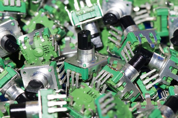
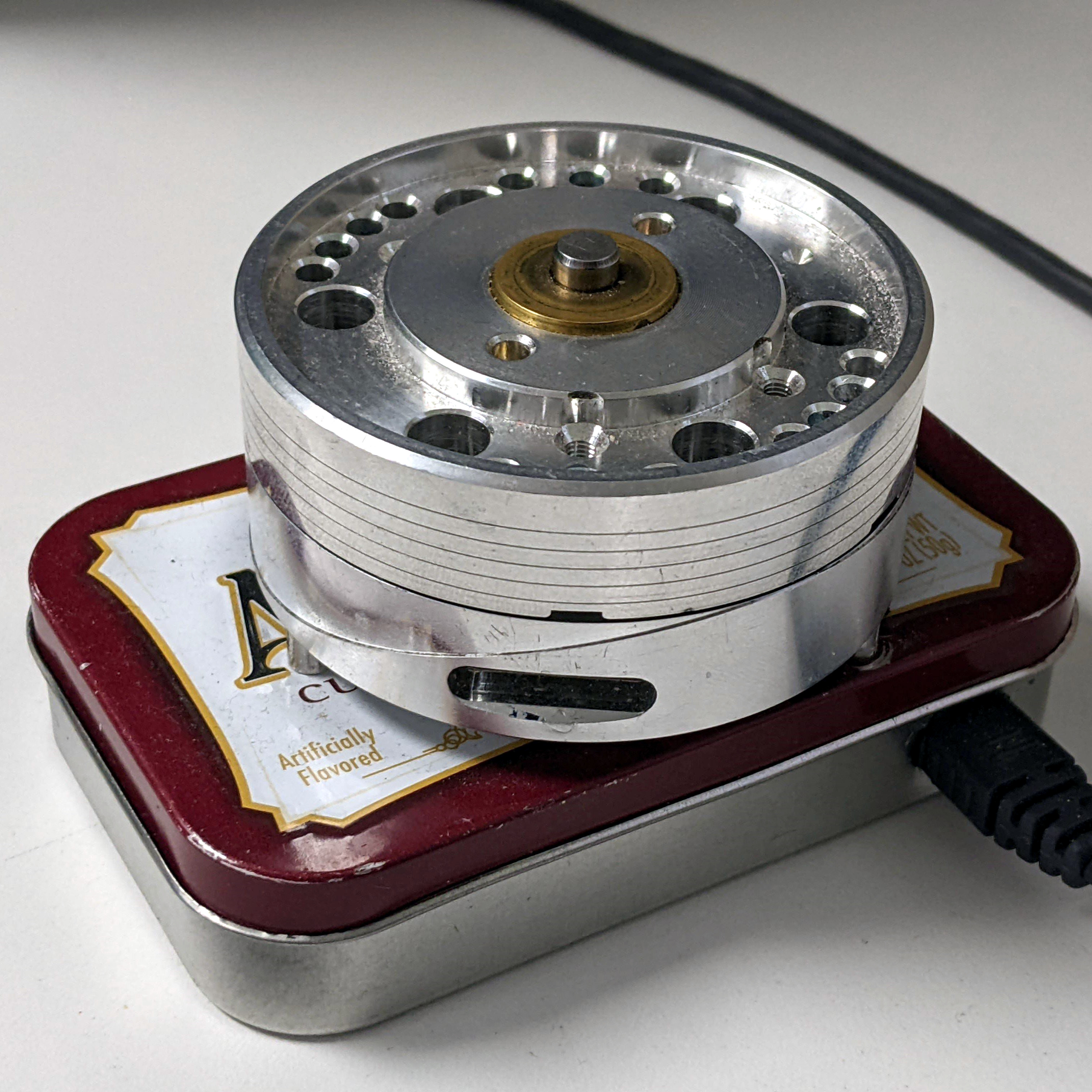
This feel-good story is one of procrastination, laziness, and one aha! moment, and it’s roughly twelve years in the making. Inspired by an Instructable from long ago, [crispernaki] ran straight to the thrift store to get a VCR and take it apart.

The original plan was to just reuse the VCR head’s PCB and hide it in an enclosure, and then figure out way to block and unblock the path between an IR emitter/receiver pair. After many disemboweled mice and fruitless attempt, the project was once again shelved.

But then, [crispernaki] remembered the magnetic rotary encoder demo board that was just sitting around, along with various microcontrollers and Altoids tins. And it all quickly came together with a Teensy 2.0 and some bits and bobs, including a magnet glued on the shaft of the VCR head. A chip on the demo board does all the heavy lifting, and of course, the Teensy does the work of emulating an HID.

Continue reading “Keebin’ With Kristina: The One With The Foot Keyboard”

A view of the inside of a car, with drivers wheel on the left and control panel in the middle, with red LED light displayed in the floor area under the drivers wheel and passenger side.

Bass Reactive LEDs For Your Car

[Stephen Carey] wanted to spruce up his car with sound reactive LEDs but couldn’t quite find the right project online. Instead, he wound up assembling a custom bass reactive LED display using an ESP32.

A schematic of the Bass LED reactive circuit, with an ESP32 on a breadboard connected to a KY-040 encoder module, a GY-MAX4466 microphone module and LED strips below.

The entirety of the build is minimal, consisting of a GY-MAX4466 electret microphone module, a KY-040 encoder for some user control and an ESP32 attached to a Neopixel strip. The only additional electronic parts are some passive resistors to limit current on the data lines and a capacitor for power line noise suppression. [Stephen] uses various enclosures from Thingiverse for the microphone, rotary encoder and ESP32 box to make sure all the modules are protected and accessible.

The magic, of course, is in the software, with the CircuitPythyon ulab library used to do the heavy lifting of creating the spectrogram and frequency filtering. [Stephen] has made the code is available on GitHub for those wanting to take a closer look.

It wasn’t very long ago that sound reactive LEDs used to be a heavy lift, requiring optimized FFT libraries or specialized components to do the spectrogram. With faster and cheaper microcontroller boards, we’re seeing many great projects, like the sensory bridge or Raspberry Pi driven LED spectrogram, that can now take spectrograms and Fourier transform calculations as basic infrastructure to build on top of them. We’re happy to see [Stephen] leverage the ESP32’s speed and various circuit Python libraries to create a very cool LED car hack.

Video after the break!

Continue reading “Bass Reactive LEDs For Your Car”

Kitchen timer project in a angled green 3d printed case with a 7 segment display and knob.

Printing A Brutalist Kitchen Timer

A kitchen timer is one of those projects that’s well defined enough to have a clear goal, but allows plenty of room for experimentation with functionality and aesthetics. [Hggh]’s exploration of the idea is a clean, Brutalist kitchen timer.

The case for [Hggh]’s kitchen timer is 3D printed with openings for a TM1637 four digit, seven segment display and for a KY-040 rotary encoder with knob attached. The internals are driven by an ATmega328P powered from a 18650 cell with a DW01-P battery protection chip and a TP4056 chip for charging. On the back of the case is a power switch and USB-C connector for power. It looks like the 3D printed case was sanded down to give it a smooth matte surface finish.

All the project files, including the STLs, OpenSCAD code, and KiCAD design, are available on GitHub. This Brutalist kitchen timer project is a nice addition to some of the kitchen timers we’ve featured in the past, including a minimalist LED matrix timer and a Nixie timer with keypad.

Arduino hearing test device overview

DIY Arduino Hearing Test Device

Hearing loss is a common problem for many – especially those who may have attended too many loud concerts in their youth. [mircemk] had recently been for a hearing test, and noticed that the procedure was actually quite straightforward. Armed with this knowledge, he decided to build his own test system and document it for others to use.

audiogram showing the results of the arduino hearing test device
Resultant audiogram from the device showing each ear in a different color

By using an Arduino to produce tones of various stepped frequencies, and gradually increasing the volume until the test subject can detect the tone, it is possible to plot an audiogram of hearing threshold sensitivity.  Testing each ear individually allows a comparison between one side and the other.

[mircemk] has built a nice miniature cabinet that holds an 8×8 matrix of WS2812 addressable RGB LEDs.  A 128×64 pixel OLED display provides user instructions, and a rotary encoder with push-button serves as the user input.

Of course, this is not a calibrated professional piece of test equipment, and a lot will depend on the quality of the earpiece used.  However, as a way to check for gross hearing issues, and as an interesting experiment, it holds a lot of promise.

There is even an extension, including a Class D audio amplifier, that allows the use of bone-conduction earpieces to help narrow down the cause of hearing loss further.

There’s some more information on bone conduction here, and we’ve covered an intriguing optical stimulation cochlear implant, too.

Continue reading “DIY Arduino Hearing Test Device”

A Rotary Encoder: How Hard Can It Be?

As you may have noticed, I’ve been working with an STM32 ARM CPU using Mbed. There was a time when Mbed was pretty simple, but a lot has changed since it has morphed into Mbed OS. Unfortunately, that means that a lot of libraries and examples you can find don’t work with the newer system.

I needed a rotary encoder — I pulled a cheap one out of one of those “49 boards for Arduino” kits you see around. Not the finest encoder in the land, I’m sure, but it should do the job. Unfortunately, Mbed OS doesn’t have a driver for an encoder and the first few third-party libraries I found either worked via polling or wouldn’t compile with the latest Mbed. Of course, reading an encoder isn’t a mysterious process. How hard can it be to write the code yourself? How hard, indeed. I thought I’d share my code and the process of how I got there.

There are many ways you can read a rotary encoder. Some are probably better than my method. Also, these cheap mechanical encoders are terrible. If you were trying to do precision work, you should probably be looking at a different technology like an optical encoder. I mention this because it is nearly impossible to read one of these flawlessly.

So my goal was simple: I wanted something interrupt driven. Most of what I found required you to periodically call some function or set up a timer interrupt. Then they built a state machine to track the encoder. That’s fine, but it means you eat up a lot of processor just to check in on the encoder even if it isn’t moving. The STM32 CPU can easily interrupt with a pin changes, so that’s what I wanted.

The Catch

The problem is, of course, that mechanical switches bounce. So you have to filter that bounce either in hardware or software. I really didn’t want to put in any extra hardware more than a capacitor, so the software would have to handle it.

I also didn’t want to use any more interrupts than absolutely necessary. The Mbed system makes it easy to handle interrupts, but there is a bit of latency. Actually, after it was all over, I measured the latency and it isn’t that bad — I’ll talk about that a little later. Regardless, I had decided to try to use only a pair of interrupts.

Continue reading “A Rotary Encoder: How Hard Can It Be?”

A DIY CAD Mouse You Can Actually Build

When you spend a lot of time on the computer doing certain more specialised tasks (no, we’re not talking about browsing cat memes on twitter) you start to think that your basic trackpad or mouse is, let’s say, lacking a certain something. We think that something may be called ‘usability’ or maybe ease-of-use? Any which way, lots of heavy CAD users gush over their favourite mouse stand-ins, and one particularly interesting class of input devices is the Space Mouse, which is essentially patented up-to-the-hilt and available only from 3DConnexion. But what about open source alternatives you can build yourselves? Enter stage left, the Orbion created by [FaqT0tum.] This simple little build combines an analog joystick with a rotary knob, with a rear button and OLED display on the front completing the user interface.

The idea is pretty straightforward; you setup the firmware with the application you want to use it with, and it emits HID events to the connected PC, replacing the mouse or keyboard input. Since your machine will take input from multiple sources, it doesn’t replace your mouse, it augments it. It may not be very accurate for detailed PCB layout work, but for moving around in a 3D view, or dialling in a video edit, this could be a very useful addition to your workstation, so why not give it a try? The wiring is simple, the parts easily found and cheap, and it’s only a few printed parts! This scribe is already printing the plastics right now, if you listen carefully you might be able to make out the sound of the Lulzbot in background.

There are many other takes on this idea, with varying levels of complexity, like this incredible build from [Ahmsville] that sadly doesn’t make the PCBs available openly, and here’s one we covered earlier mashing the expensive 3DConnexion spacemouse into a keeb.

Continue reading “A DIY CAD Mouse You Can Actually Build”

3D Printed Absolute Encoder Is Absolutely Wonderful

When you need to record the angle of something rotating, whether it’s a knob or a joint in a robotic arm, absolute rotary encoders are almost always the way to go. They’re cheap, they’re readily available, and it turns out you can make a pretty fantastic one out of a magnetic sensor, a zip tie, and a skateboard bearing.

When [Scott Bezek] got his hands on a AS5600 magnet sensor breakout board, that’s just what he did. The sensor itself is an IC situated in the middle of the board, which in Scott’s design sits on a 3D-printed carrier. A bearing mount sits atop it, which holds — you guessed it — a bearing. Specifically a standard 608 skateboard bearing, which is snapped into the mount and held securely by a zip tie cinched around the mount’s tabs. The final part is a 3D-printed knob with a tiny magnet embedded within, perpendicular to the axis of rotation. The knob slides into the bearing and the AS5600 reads the orientation of the magnet.

Of course, if you just wanted a rotary knob you could have just purchased an encoder and been done with it, but this method has its advantages. Maybe you can’t fit a commercially-available encoder in your design. Maybe you need the super-smooth rotation provided by the bearing. Or maybe you’re actually building that robotic arm — custom magnetic encoders like this one are extremely common in actuator design, and while the more industrial versions (usually) have fewer zip ties, [Scott]’s design would fit right in.

Continue reading “3D Printed Absolute Encoder Is Absolutely Wonderful”