While most countries have switched to digital broadcasting, and most broadcasts themselves have programming on 24/7 now, it’s hard to remember the ancient times of analog broadcasts that would eventually stop sometime late at night, displaying a test pattern instead of infomercials or reruns of an old sitcom. They were useful for various technical reasons including calibrating the analog signals. Some test patterns were simply camera feeds of physical cards, but if you wanted the most accurate and reliable test patterns you’d need a Philips pattern generator which created the pattern with hardware instead, and you can build your own now because the designs for these devices were recently open-sourced.
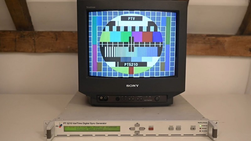
[Matt] from [Matt’s TV Barn], as the name implies, has an interest in various television technologies, and this is such an iconic piece of machinery that can’t easily be purchased, so he set about recreating the signal generator on his own. All of the source for these cards can be found at this GitHub page for anyone interested, and most of the parts can still be found today. The main exception being the adjustable inductors, which [Matt] needed to build from scratch. Soldering everything to the board was a bit nerve-wracking but with the help of a robotic lifter (and a lot of patience) the board was soldered without any damage.
The final step of the build is to get everything up and running by following the original testing and commissioning procedures that were developed and released by the original company that built these devices. This was a feat in its own right, as there are a large number of complex tools needed to perform these operations that [Matt] plans to talk about in future videos, but with everything completed he has a piece of TV history that’s about as authentic as anyone could possibly get anymore. You don’t have to go to these lengths to get the aesthetic of analog TV, though. Take a look at this restored analog TV that uses a Raspberry Pi to generate its analog signals.


And one that generated the Indian head picture.
What is an indian head picture? Is’nt that supposed to be disciminazing and “forbidden” or out of fashion?
Maybe just call it PM5544
https://en.wikipedia.org/wiki/Test_card#/media/File:Philips_PM5544.svg
https://en.wikipedia.org/wiki/Indian-head_test_pattern
I think you mean this:
https://upload.wikimedia.org/wikipedia/commons/thumb/a/ac/Indian_Head_Test_Pattern_with_Labels.png/800px-Indian_Head_Test_Pattern_with_Labels.png
My favorite is still the old monochrome test pattern generators which were basically a big CRT sealed in a box with the “indian head” pattern etched on a plate of metal in the middle, which blocked the electron beam as it scanned over it and created dark patches in the signal picked up on the other side. Wish I had one:
https://hackaday.com/2019/05/26/vintage-monoscope-tubes-generate-classic-tv-test-patterns-once-again/
“While most… it’s hard to remember…”
That… isn’t the right statement.
Do you mean EASY to remember?
Easy to forget?
Hard to forget?
Those all make different statements, but I can’t tell which one you actually mean.
Yeah, I tripped over this line too. I think it’s supposed to be something like “While … we can still remember …”
As hillary said,
“What difference does it make?
Make (at least non-cracked version) is probably way faster than cobbled together batch or python scripts.
I wonder, a large enough memory to store all the pixels, add a counter chip set to loop through the memory at the right speed, a little bit of discreet component glue and plug it straight into the antenna or component video. Low parts count, provided the clock was accurate and you could adjust the phase, it might be an easier way to make a test pattern, it might even fit into a mint tin.
Assuming you can even find an old analog TV to test the test pattern generator..
That’s true for analog NTSC/PAL color TVs, maybe.
Higher end black/white TVs are held in high regards, though.
They make nice pieces of furniture or decoration items.
Also, they’re more reliable and can easily be restored (by comparison).
The rest of his channel is pretty great too! I just watched a NICAM stereo over-the-air transmitter, possibly the only one in existence….
Wow, I remember playing with GV sync gens. They put out a test pattern too.
UK satellite service Sky TV has a test card for 4k-UHD – HDR. The purpose of the test card is to demonstrate the tv panel and the connected Sky Q digibox is set up to view HDR. If the tv panel or Sky Q digibox is not set up properly, the 4k-UHD – HDR test card will not be displayed.
Lovely old test patterns (or test cards in the UK). I liked the tweaks they made to Test Card F when they made Test Card J, like re-centering the image so the X was exactly in the middle of the screen, and you could see that the clown actually had chalk!
And then there’s Ceefax In Vision, which was how you could pretend you had a Teletext TV if you couldn’t afford one. 😃
Some video cassette recorders had a testbild generator, too..
I vaguely remember that they had a little switch on the back to enable that generator.
There’s more to it than that…it’s the analog part of the TV that needs to be tested as well…there’s a filter, IIRC, that separates the color burst and subcarrier from high frequency dots. Part of the test pattern is how well those high frequency dots are resolved and what the breakpoint is between the dots and the color subcarrier. There’s also a test for color carrier phase accuracy and the time it takes to transition over the greatest subcarrier phase difference…there are two bars in the color test that, if you look closely at where they join, there will be a small gap…that’s the place.
All the above is from memory, quite a while ago I investigated the test pattern. An old HP or Philips catalog might have the data on what is testable with these generators.
…and Wikipedia, of course, has loads of info on test patterns, the Philips generator, and test cards.
For ’90s NTSC test pattern generation, consider the Newtek Calibar. Lab grade but fits in a shirt pocket like a fat pen. Nice!
All old hardwares should be open sourced like this! Including MCU firmwares, PAL/GAL/FPGA programming…
I have for example on ald Sony EV-S9000E Hi8 VTR that is completely unusable only because a small MCU, mainly in charge of power management and LCD display, is dead. It could be replaced by some other one, except that this MCU was with integrated OTP memory, with a specific “firmware” now impossible to find anywhere…
And being able to restore/clone old hardware is something important both for archive preservation (audio, video, data…) and technology history.
I found at NV back in the early 2000’s that our analog / digital Philips test equipment (VM200?) and a newly designed National Instruments ADC box we built for lab qualification, had a color bar error in excess of 2.2 degrees in almost opposite directions. I had to use a scope (10GHz), Excel, and some convolutions to measure the phase and amplitude, and finally tweaked the analog generator parameters down to 0.3% (best we could do with limited digital knobs). Just another day at the job…
Oh, and the IP block we bought came with a DVD, which we found out, was recorded by a pocket VCR from a printed colorbar, and relabelled by their marketing team as a Calibration disk.
Beautiful work, by a skilled engineer, with the right tools – and a lot of patience.
Congratulations on a job well done.