
The current state of the art of embedded motion sensing is based around micro-electromechanical systems (MEMS) devices. These miracles of microfabrication use tiny silicon structures, configured to detect acceleration and rotational velocity in three dimensions. Accumulate these accelerations and rotations, and you’ve got a device that can find its orientation and track movement without any external waypoints. This is the basis of the technique of dead reckoning.
Why do we care about dead reckoning anyway? Surely GPS and related positioning systems are good enough? Above ground GPS is usually good enough, but underwater and underground this simply won’t work. Even heading indoors has a dramatic effect on the GPS signal strength, so yes, we need another way for some applications.
Right now, the current state of the art in portable sensors are MEMS devices, and you can get them for the cost of a hamburger. But if you want the ultimate in accuracy, you’ll want a quantum atomic interferometer. What that is, and how it will be possible to make one small enough to be useful, is half of the story. But first, let’s talk MEMS.
Fusion of The Sensors
Given an initial position and accumulated accelerations in 3D, it is possible to track position, for a short while at least. According to this (outdated) Cambridge University report on Inertial navigation systems, with a MEMS-based inertial tracking system, positional error can exceed 150 meters in under a minute, because the errors don’t average out, they accumulate.
Improvements can be made by fusing data from other sensors into the navigation model. It all depends on where you are; here on earth such additional data inputs could be taken from a magnetometer, and also an altimeter. It has been shown that adding the magnetometer data alone can reduce that 150 meter error to only 5 meters. The study is a few years old, but we expect it to be about right, as progress with MEMS technology has not improved all that much.
Want to see how good or bad inertial navigation is in real life? A fantastic device for doing all this complicated multi-sensor fusion stuff is the Bosch BNO055, for which Adafruit have helpfully popped on a module. You just might want to brush up on quaternions before you do, mind.
All these measurements will exhibit an error, which will have some particular statistical distribution. One technique to mitigate this error is by using Kalman filtering, which is used heavily by inertial navigation systems. A Kalman filter enables a better understanding of the unknowns in a model, and essentially adjusts itself over time, to allow more influence from measurement points with the least uncertainty. The result is hopefully a better positional fix and an idea of which way you’re currently pointing. But, you still can’t get away with it for long, the error is still there, and it will still accumulate given enough time. Current research seems to suggest an error figure of about 5% of total distance travelled, best case. Longer term, sub-meter inertial navigation is the goal, and we aren’t there yet.
MEMS Sensors: Sources of Error
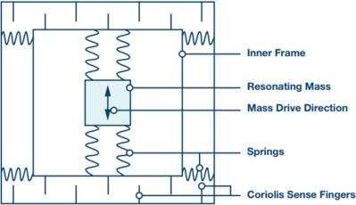
The MEMS gyro is a dynamic device, in that it consists of a tiny vibrating structure that detects angular rotation rate by leveraging the coriolis effect. A mechanical shift is induced orthogonal to the vibration direction, which is sensed as a small change in capacitance.
Gyro sensors typically exhibit two main kinds of error; a rate bias and an angle random walk error, the latter is due to thermo-mechanical white noise and flicker noise in the signal chain electronics. The random walk error grows with time, which is what contributes mostly to the overall absolute orientation error. The rate bias however can be measured long-term and largely cancelled out. There are some other so-called calibration effects that affect stability and will also contribute error terms that are harder to compensate for.
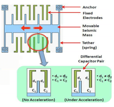
The MEMS accelerometer has a more static structure, and is essentially a sprung element which deflects in one axis to due to acceleration. This mechanical shift is also picked up as a tiny change in capacitance. Again, we have the same two main sources of error; acceleration bias error and velocity random walk error. The bias error now is more complicated, because on this planet we have gravity, and in order to cancel out the bias error, we need to know the orientation of the sensor. Luckily with a multi-sensor fusion system, the orientation can be measured and this bias can be compensated. The velocity random walk error is again due to thermo-mechanical effects and accumulates with time. Also, as with the gyro, there are additional error factors that add to problem.
Other sensors used for inertial navigation systems will all have their own sources of error, and add to the complexity of the problem. There are optical gyros available, for example the ring laser gyro, and more esoteric devices, but these are not necessarily easy to make really small. For example, the ring laser gyro is less accurate the smaller you make it due to the limit in the maximum beam path length. This is why current research is taking a very different approach to this type of sensing; namely the atom interferometer.
Atom Interferometry
Back in 1924 French physicist Louis de Broglie proposed that matter behaves like a wave, with a wavelength equal to the Planck constant divided by its momentum. This meant that just like light, matter waves can be diffracted and produce interference patterns. In this case matter waves are manipulated with lasers, which leads us into the fun part. Remember though, that unlike light, atoms are massive and such, gravity has an influence, as we shall see.
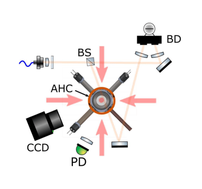
Most atom interferometer experiments seem to operate similarly, in that they all depend upon a high vacuum pressure vessel, and utilise a magneto-optical trap to cool and slow down a stream of rubidium atoms produced from some source. This device uses six intersecting, circularly polarised laser beams, aimed at the centre of the device, with a pair of anti-Helmholtz coils at the top and bottom.
A Helmholtz coil is configured to generate a uniform magnetic field, using a single pair of coils, with current flowing in the same direction. The anti-Helmholtz coil (aka Maxwell gradient coil) simply flips one of the coils over, to produce a magnetic field gradient, with a field zero at the centre. Exactly what we need to trap those pesky little atoms.
The photons from the containment lasers give the atoms a little kick in momentum, and due to the Zeeman effect, the specially-shaped magnetic field ensures that atoms are more likely to get pushed back towards the optical null in the centre of the trap. On average the atoms in the trap centre slow down enough to reach temperatures of a few micro-kelvin. Which is jolly chilly.
The next bit is where things get a bit freaky. The trap is turned off, and immediately each of the suitably frigid atoms is hit with a specially prepared laser pulse, formed by a pair of opposing lasers, either Raman or Bragg transitions are effected, depending on the properties of the laser pulses. The atoms are forced into a quantum superposition of being both hit and not hit by the pulse. This causes the atoms to change momentum and state. (And not, simultaneously, it’s superposition of states, right?) The atom cloud diverges and depending on the motion of the cell, interferes with itself as it expands out from trap centre.
When a low power laser illuminates the atom cloud, the superposition collapses and the interference pattern is observed on a suitably placed CCD. By decoding this pattern it is possible to infer angular velocity as well as acceleration, with incredible accuracy that will open up new applications both on earth and beyond. NASA are interested for one. For more detail on atom interferometry, checkout this introduction from Berkeley Physics.
Practicality
All of this is of little use as a navigation device if you can’t get it out of the lab and shrink it down in size, make it reliable and make it cheap. Sounds easy, right? Let’s look at the requirements for an atomic gyroscope: you need a pressure vessel with optically pure windows, usually sapphire, that can maintain a pressure of less than 10-7 torr with very low contamination. You also need the lasers themselves, with associated filters and control electronics. All of those things can be miniaturized, even down to chip size, but maintaining that vacuum is a big challenge. The usual way to get down to such low vacuum pressure is with a turbomolecular pump, in combination by an ion pump. Making these smaller has proved problematic.
A Passive Pumped Vacuum Package
Now there is a possibility of removing the need for that complex and bulky vacuum system. A team from Sandia National Laboratories and the University of Oklahoma, have developed a technique for achieving the ultra-high vacuum (UHV) needed for inertial guidance atomic gyroscope applications, without the need for turbo pumps, ion pumps or any pumps at all. OK, that last bit isn’t strictly true, as they needed to get the vacuum to the desired level first and the standard techniques were needed for that, but once the initial conditions were achieved, the pressure vessel could be sealed off permanently, and the pumps removed.
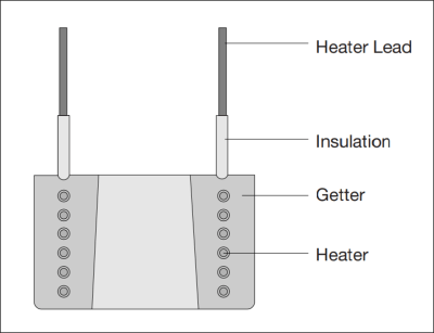
The system relies on chemisorption using sintered porous getters, which are a kind of non-evaporable getter (NEG). These simple passive devices are formed from a sintered porous structure of zirconium powder and other materials, wrapped around an electrical heating element. When manufactured they are exposed to air, forming a passivating coating and protecting them from contamination. When installed in a vacuum chamber, the getter is activated by heating it up during the pump-down process. This diffuses the passivation layer into the bulk of the structure and provides an activated surface ready for adsorbing any contaminants during pump-down and afterwards when the chamber is sealed off. Getters are pretty common in many household vacuum vessel devices, from incandescent light bulbs, to radio valves, but the getters used here are a little bit more specialised than those of old, and capable of grabbing more atoms over a longer period and keep them contained.
The whole point here is that in order to have a small pure group of super cool rubidium atoms to poke with lasers, you first need to not have any other atoms kicking around, getting in the way. Such getters are super important for grabbing rogue atoms and maintaining this purity.
Outgassing is a problem with ultra-high vacuum devices. Contaminant gasses present in the structure of the housing diffuse out into the pressure vessel, contaminating the vacuum. Another related issue is that of permeation from the outside of the vessel. NEG devices work on chemical principles, so any helium that manages to diffuse into the vacuum from outside the enclosure will not react with the getter, and will contaminate the vacuum. Both of these problems were minimised by careful selection of materials. The frame was made from pure titanium, which had a low hydrogen content, with the windows made from sapphire, which apparently has no measurable helium permeability. These two materials have closely matched thermal expansion coefficients, which helps to maintain the vacuum seal and reduce stress on the structure as the temperature drops.
The team found that once pumped-down and sealed the ‘passively pumped’ vessel could maintain the 10e-9 torr vacuum pressure needed for over 200 days, and that means if all the other components could be successfully miniaturised, there is now a path to producing the first small and therefore portable MOT, and with it an atom interferometer capable of inertial guidance applications. Of course, since the application here is essentially an accelerometer, it can be used as a super-sensitive gravimeter which would be useful for ground surveying for sectors such as oil and mineral exploration as well as for geological research.


Whose hamburger? Big difference between a designer burger at an expensive bistro versus a happy meal
At the moment it costs more than a designer hamburger if you can find them to buy.
Does the “expensive bistro” burger come with a toy?
No it doesn’t. That’s generally how you tell it is anexpensive bistro
Don’t they include IMU breakout boards in Happy Meals yet? Where’s my flying car?
It seems as far as Kalman filtering goes, it might be useful to use several filters in parallel, with a sliding scale of gain with respect to the reference model, then compare the results, giving you an estimation of how noisy the signal is and then dynamically switching between filter results to suit your needs.
If applied to say, a video image, it could sharpen edges and get rid of grain to increase contrast, giving a stained glass window like effect, making it easier to detect objects, but when suddenly bringing in another object, it wouldn’t try to blur it with the original, but instead apply the same formatting to the new example. Then again there’s nothing to stop this also being applied to speech recognition or single sensor inputs like photo transistors or sonar rx.
I am not a university maths person. I have read this article and the Wikipedia article on Kalman filters. It sounds like they compare calculated position to measured position. But I thought dead reckoning meant having no position measurements. So how does this work?
Haven’t had time to read the report on errors (this weekend maybe), but what about averaging large numbers of MEMS devices; start with 100, then maybe 1000. That’s still a small volume for a sub or aircraft.
I would love an article that explained how Kalman filtering works without getting mired into a turtles-all-the-way-down mathematical exercise. I recall the endless examples of functions to drive Bezier curves only to find that they are generated with a simple algorithm of linear interpolation of a linear interpolation.
Yep, it often feels like math aficionados are just waiting for an opportunity to dump all their very specialized domain knowledge onto you, when it would suffice to really cut out a small portion of it, and simplify it accordingly.
A problem of academia in general.
The credo should me: explain it as simple as possible and what is necessary, expand on that later.
Usually you do the opposite in academia. Introduce a topic very broadly and generally, then bring a practical application (if lucky). By the time you finally reach the specific info you were looking for, you forgot the overall abstract ideas, since they are just too many and not anchored by easy enough practical examples of immediate need.
It’s almost as if they are afraid you wont dive into a topic deeper, if they dont force it on you from the get go.
As long as its got layman terms and the connections between each element creates a clear overview of the subject I’d rather have a dive in at the deep end – you need to know the basic structure of the subject for it to make any sense, but if/when some part of the info dump goes over your head you at least have heard the right terms, have some idea of what that bit is about even if you don’t really understand it, so if/when such a concept might prove to be useful you hopefully remember enough to find an expert consultant or take the time to study that bit yourself.
The main difficulty understanding the kalman filter comes from the need to describing it formally rather than informally as here.
Informally a simple one input Kalman filter is just an advanced form of a weighted average filter summing two weighted inputs consisting of your prediction of what the next input is and a measurement of what the next input is. If you have more faith in the prediction you give it a higher weight. If you have more faith in the measurement, you give it a higher weight. (Both weights add up to 1).
The clever/difficult part of the kalman filter is that it uses an algorithm (using the cumulative accuracy of the prediction, and the accuracy of the new measurement) to optimise the weights after each pass through the filter.
For a very simple example, a weighing scale ( a static case ; the weight doesnt change). If you have no previous inputs, the measured mass will have a 100% weight, the predicted mass 0%. However after each pass you can be more confident of the prediction so the weight given to the previous result(prediction) increases and the weight given to the measurement reduces, until you reach a point where the weight given to a new measurement is so small that it makes no noticeable difference.
In dynamic cases ( e.g reading a position sensor) you can never give full weight to the prediction of course, but for a hobby project, before delving into the complexities, you can get good results just experimenting with constant weights to start with,IOW a digital low pass filter. This works quite well as an approximation since often a kalman filter’s weights will level out to be more or less constant after many passes. To progress from the constant weights to a true kalman filter just involves knowing the measurement error and applying the weighting algorithm to derive the next weights.
The article mentions needing 10^-7 torr, and then later when referring to the Sandia experiment, says 10^-9 was needed. So which is it?
The coefficient of thermal expansion of titanium is not matched to sapphire. Titanium is ~9 ppm/°C, and sapphire is ~6 ppm/°C (both are dependent on temperature, and single crystal sapphire is also dependent on crystal orientation). That might not sound like much, but if you need to heat the materials up to several hundred degrees C to create a glass or brazed seal, those thermal stresses can be significant.
Any link to the paper/article from the Sandia experiment?
Thanks for pointing out that I completely missed posting the link to the paper. Article updated.
or Direct link
Thank you! I didn’t say it before, but I really enjoyed the article.