Will Knecht•Stephen Penney •Graham Collier
UniversalPegasus International
The dawn of the 21st century does not seem like a long time ago. The late 1990s and early 2000s were a time before many people had a dial-up modem let alone a dedicated broadband connection. In fact, a basic smart phone today has 10 times more processing power than a personal computer did back then. Fax machines and copiers went through paper without remorse, whereas now the boxes of binders a project engineer once took offshore have been replaced by laptops and external hard drives.
In fact, the transmission and storage of information now is so effortless as to be trivial in the grand scheme of things. While the document control process is certainly far from trivial, the passing of information from one gatekeeper to another is no longer a process involving paper cuts, cardboard boxes, file cabinets, or folders - well, at least not as many. Documents and drawings can be easily archived to “the cloud” for convenient storage and retrieval. A mere 10 years ago, boxes of original documents (and their draft copies) would be shipped weekly to corporate storage facilities where they were quickly forgotten. In some instances, this archaic practice is still being implemented today; old habits indeed die hard.

Imagine the frustration when about 20 years after a pipeline end termination (PLET) or a rigid jumper was installed - and - spoiled by the luxury of new technology - an exhaustive search for archived information only results in an old scan of hand sketch, a rudimentary fabrication drawing, and a few photos of the structure taken at the fabrication yard. Unfortunately, the handful of people who may have known where to find the coveted information are no longer with the company, and even if they were - it would take several weeks rummaging around a storage facility for one of them to find it, even if it existed at all.
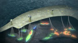
So begins the process of engineering a decommissioning project, and each of these projects will come with its fair share of surprises. The initial incompleteness of the information available to the project team (and the questionable accuracy of the information) is the first hurdle to overcome. This was the case on a 2015 project in which our project team oversaw the engineering and offshore operations for the decommissioning of several rigid jumpers, flying leads, and other subsea architecture.
An excellent starting point when it comes to tracking down information is the Bureau of Safety and Environmental Enforcement (BSEE) website. Here a wide range of information may be discovered, including as-built drawings and field layouts with relevant segment numbers. It is important to note that BSEE records can only be as complete as the information they are given. In this case, the search for information only started with BSEE. It took a small archaeological expedition to find the rest of the information, if it existed at all.

The aforementioned project will be drawn upon for much of the information presented in this article, thus the following is a brief explanation of the work that was performed. The project consisted of the disconnection and recovery of three rigid jumpers, several hydraulic flying leads (HFLs), and a few electrical flying leads (EFLs) to enable the trees to be recovered. Two of the rigid jumpers (Jumpers A and B) were connected to their respective hubs via flanged connections and were installed in the 1990s by divers in 1,500 ft (457.2 m) water depth using an Oceaneering International Inc. atmospheric diving suit (ADS). Following the disconnection of the flanged jumpers, flanged pressure caps were installed on the empty flanges to provide isolation from the environment.
The third jumper (Jumper C) had diverless vertical connectors (DVC). The empty PLET and tree hubs were isolated from the environment with modified hub pressure test clamps following the recovery of the jumper. Typically, purpose-built pressure caps would be used, but these could not be fabricated to meet the project timeline.
One consideration worth highlighting when it comes to decommissioning projects is that they are never a simple matter of reverse engineering. In all likelihood, the components of a subsea field were not designed or installed with the intent to return 20 years later and recover everything. Furthermore, in many cases there may be other wells as part of the development that share common flowlines, PLETs, hydraulic and electrical controls. These wells/trees may remain in service, so additional care is required to prevent field shut-ins beyond what is required for the decommissioning scopes of work.
Path forward
Jumpers A and B were installed roughly around the time that vertical connectors first entered the market. It bears mentioning that the tasks that were once a challenge for ROVs gave birth to innovations such as the diverless vertical connector. However, more dexterous ROV manipulators, more horsepower, and better ROV pilots make it possible to perform tasks that were typically allocated to divers 20 years ago. Prior to vertical connector innovation, the tried and true flange was the only way to connect subsea jumpers and spool pieces. Needless to say, divers were the best-suited means to successfully guide eight bolts into their respective holes and ensure that they were torqued to the proper value. As offshore exploration moved into deeper waters, it became apparent that a diverless vertical connector solution was the way forward. In fact, it would be hard-pressed to find a modern subsea development that did not use vertical connectors of some kind.

The century of collective experience available to the project team did include prior ADS projects. However, in the time that had elapsed since the initial installation of Jumpers A and B, atmospheric diving systems were typically not rated for use commercially at depths greater than 1,200 ft seawater. The only remaining option was to perform the work with an ROV. Initially, this seemed like a daunting task, but only for lack of certainty and experience in that it had not been done before. The project team reduced this uncertainty by closely overseeing the design of the tooling and equipment procured from Oceaneering. This included the flanged pressure caps, ROV-operated torque wrenches, ROV-operated bolt cutters and nut extractors, and contingency bolt-retaining collars. The existing PLETs and trees to which Jumpers A and B were connected were installed with bolt-retaining collars already in-place. The plan was to re-use the existing bolts, but we did not have full confidence in the integrity of the ~15 to 20-year-old collars. As such, in the event that the existing collars failed, the team would be forced to replace it subsea with the ROV.
Factory acceptance testing (FAT) was conducted upon the completion of all fabricated equipment at Oceaneering’s testing facility in Houston. System integration and function was performed to demonstrate that equipment manufacturing and operation met design requirements. Lessons learned were captured and minor modifications to the equipment and tooling were made as necessary to improve functionality and future offshore success.

To gain further confidence in the equipment and procedures, an underwater system integration test (SIT) was performed by Oceaneering at the NASA Neutral Buoyancy Laboratory in Houston. For two days the team worked alongside astronauts simulating our respective missions, missions that would later take place more than 230 mi (370 km) apart in equally remote conditions.
When it comes to installation, existing procedures are typically used for “inspiration” as cut and paste “go-bys” that may not evolve much from project to project. However, a decommissioning project is likely going to start from a blank slate, as was the case with the decommissioning of Jumpers A and B. Over the course of two days, engineered task plan methodology was performed with an ROV to simulate actual offshore operations to prove the execution process and equipment functionality. The underwater SIT proved invaluable, as the ROV maneuvered, installed, and function tested all equipment several times. Operational lessons learned were applied to the procedure, and the equipment was modified as necessary to improve future offshore success.
Offshore execution
The underwater SIT was successful in that it increased confidence in the tooling and methodology. With the exception of one unexpected discrepancy in the configuration of one of the tree hubs and its existing nut retaining collar, the offshore execution of the work went well. A discrepancy was discovered during the attempted installation of a pressure cap on one of the empty tree hubs. The pressure cap’s guide funnel was designed to fit over the existing bolt retaining clamp on the structure, which was expected to be clamped onto the piping directly underneath the flange itself. In the case of the hub in question, the nut retaining collar actually clamped around the flange. Note that this revelation would have been unlikely discovered until after the jumper had been removed. This is an excellent example of what was found verses what was expected. In this case, the change had never been recorded in as-built documentation that was readily available or accessible to the project team.

As a result of all the extensive research, physical trials, detailed planning, and a few minor infield modifications, the work was executed flawlessly. The average time for the disconnection of a single flanged connection was roughly 30 minutes. Installation of the tree and PLET pressure caps was achieved in tandem, as both ROVs worked simultaneously, each at its own hub. Using the manipulator-held socket tool, it took an average of 40 minutes to wind down all eight bolts. The final make-up torque required three passes with the hydraulic torque wrench in a typical star pattern. Each pass the torque value was incrementally increased until the final torque value was achieved. One pass with the hydraulic wrench took approximately an hour to complete, for a total of three hours. To summarize, the complete installation of one flanged pressure cap took less than five hours.
There were certainly lessons learned from the decommissioning of Jumpers A and B. While a site survey had been conducted prior to the engineering phase of the project, perhaps it would have been wise to have taken some measurements to confirm the validity of existing information. A comparative study of different hub photos taken via an ROV manipulator camera may have revealed the discrepancy in nut retaining collar configuration, something that would have been useful to know in advance of pressure cap fabrication. Fortunately, a qualified welder was part of the offshore crew. Otherwise, the modifications made to the pressure cap in the field would not have been possible. This is something worth considering in projects involving equipment that has been fabricated based on incomplete or uncertain information.
Problem solving
Typically, decommissioning of a field will involve the plug and abandonment (P&A) of one or more wells. In order to satisfy BSEE requirements that trees be monitored as long as possible, our decommissioning efforts were timed to meet the schedule of the drilling rig performing the P&A work. Thus, the decommissioning of Jumper C took place several months after the decommissioning of Jumpers A and B.

To ensure the safest offshore operations, it was decided that Jumper C would be cut subsea such that the middle portion could be removed independently of the two DVC connector pieces. This also eliminated the need for a spreader bar, jumper stands, and made the entire recovery operation far less weather dependent. An additional benefit to this strategy was that it would require the rental of just one running tool. The offshore execution of the work went according to plan with no accidents or incidents, but it is what took place following the decommissioning of Jumper C that will be of particular interest.
As mentioned earlier, a short project timeline meant that standard pressure caps could not be fabricated in advance of the offshore campaign, and there were not any existing pressure caps available in company inventory. The workaround for this dilemma was to modify two test clamps (typically used to test the integrity of the hubs). These clamps are designed to be installed and handled by technicians in a workshop, not by an ROV subsea. In order to make the clamp ROV-installable, several sets of ROV grab bars were incorporated into the clamp half-shells such that they could easily be pushed together by two ROVs. A manipulator-held socket wrench would then be used to wind down the bolts such that they could be fully torqued with a calibrated hytorc wrench, also modified to be used by the ROV.

Conclusion
Reflecting on the success of these decommissioning campaigns has raised some ideas worth contemplation. Given the improvements to ROV functionality and tooling, is there a cost-savings benefit to the use of flanges instead of more expensive alternatives? Will a few hours of vessel time spent torqueing bolts make more sense than the price of a more sophisticated option? These questions can only be answered through a detailed front-end engineering and design study, as every project is different. Moreover, when a project team is faced with old, outdated technology, it is still possible to provide a modern approach to project engineering and planning. This requires a “start again” strategy that applies to the design of new equipment and especially to the writing of new procedures. A realistic, physical SIT is ultimately the best way to refine procedural methodology and to identify potential issues with newly designed equipment. Subsea field decommissioning projects will be laden with unknowns, but fortunately you do not have to be an astronaut to get to the bottom of it.